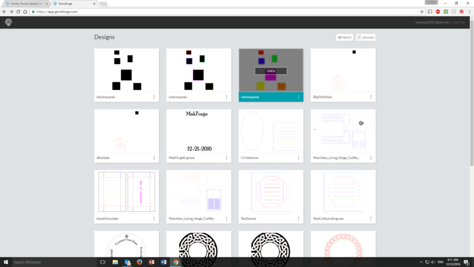
Saw a post from Laserbits show up on Facebook today promoting a free power/speed grid they have for download. It’s a CorelDraw file however Inkscape will open it.
The idea behind it is you run this grid onto a sample of each material you plan to use, and it becomes a handy visual chart for the effect you’re looking for with each project.
It is an intersting challenge to make a file that tests non ProofGrade material in a Glowforge. I am not sure how another brand of lasers would parse that file, but it really wouldn’t work for a Glowforge.
So you need a file with about some different colored boxes for the stroke and then make the fill black. That will give you say six different squares. Then you can make designate the process for each square separately.
I’ll make something up tomorrow. I have a couple small test images I am using for testing cuts and scores on non-proofgrade leather (vegetable tanned). Stay tuned.
You don’t need a fill (at least on other machines) as the engrave of the stroke color will engrave everything inside the boundary of that color’s box. But you’ll end up with a ton of colors with shades that are going to be close to each other. So when you set it up, make them all black strokes. Then color each box’s outline and set the power/speed right then. (In my laser software it shows a color/operation stack on the right and as I add colors to the design they pop up in the stack. Not sure how you’ll do that in the GF.) By making the box color and setting the parameters right away you don’t lose track of similar colors. Otherwise you’ve got 100 colors in your stack to assign power/speed settings to and can’t tell which one is which
In my laser’s software I can specify the RGB values so I could do thousands but the difference between 200/210/210 (RGB) and 200/210/220 is hard to see visually
The Glowforge treats it a little differently, at least for now. I’ll clean up this file and write some settings on the file itself, but this is just to demonstrate. Here is a screenshot of a pattern of squares that have the stroke and fill each treated differently. From top left to right: Black stroke; black fill; colored stroke, black fill; colored stroke, colored fill. The import treats each of these separately. You might have to zoom in to note the differences.
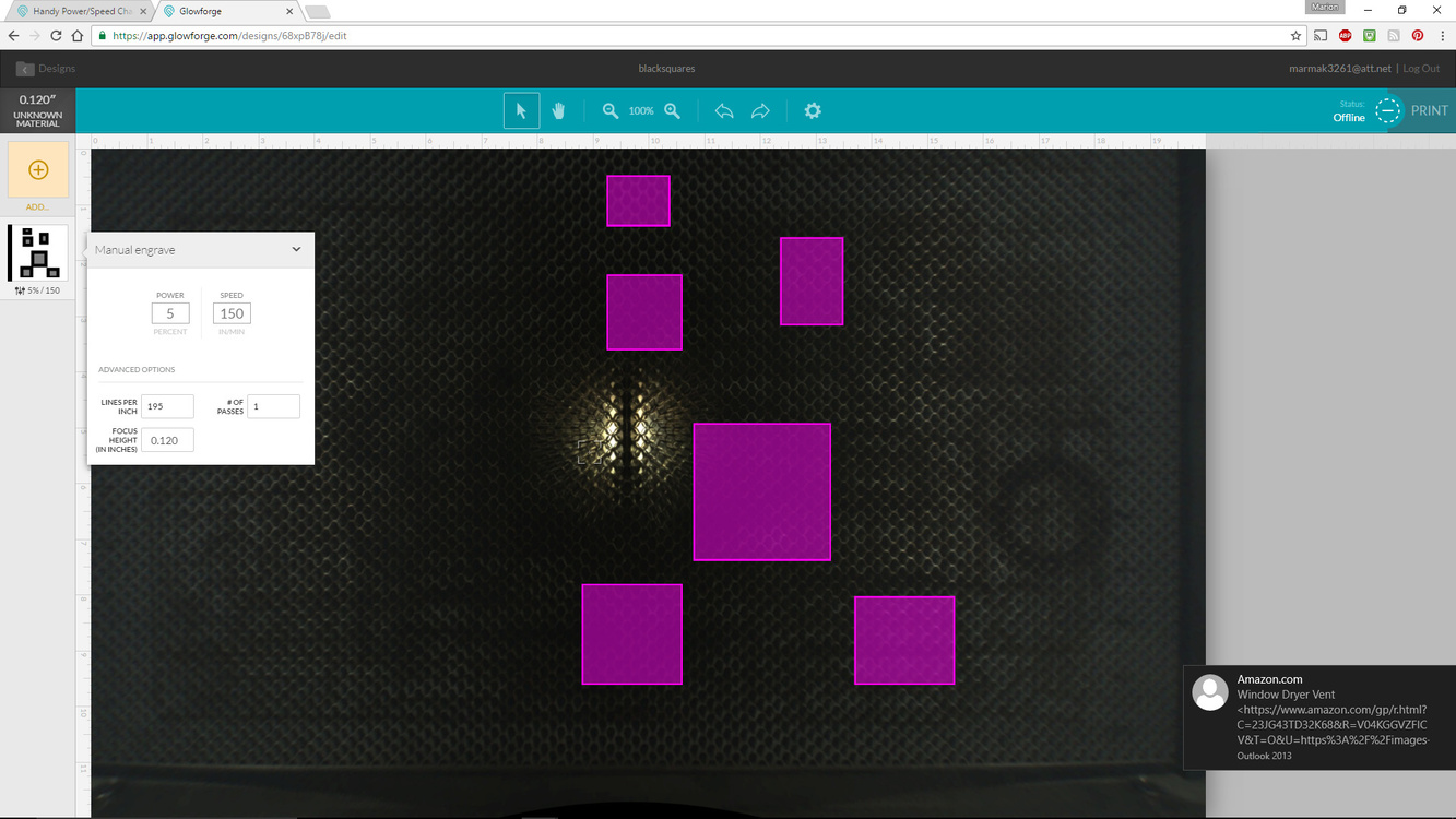
In the first case with black stroke, black fill, all the squares are treated as one and you have only one choice of engrave.
Here is the result of opening the design. I designated the engraving values myself.
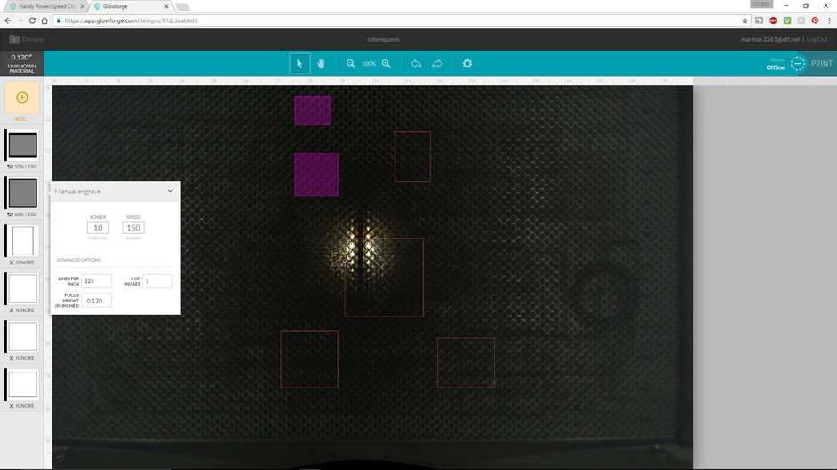
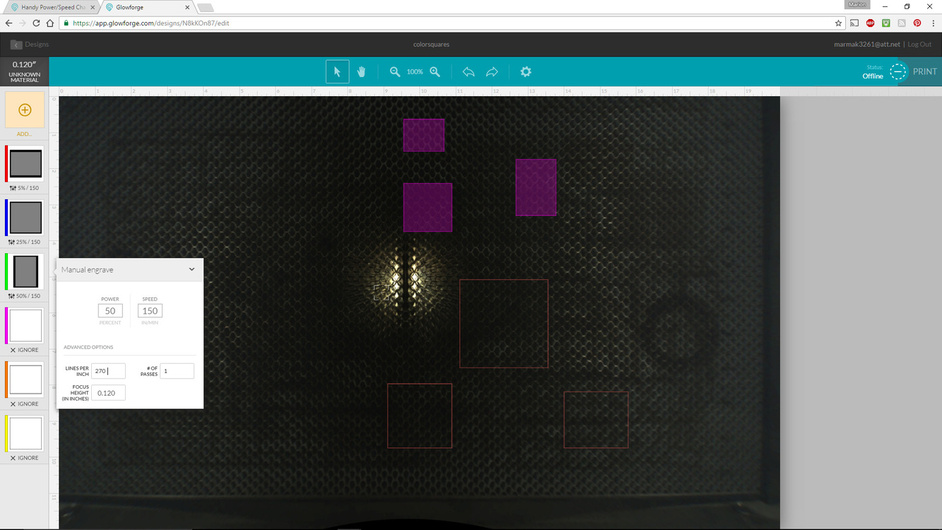
In the case of the second from the top left, color stroke, black fill this is what you get after opening. Note that now each box has a separate operation. Of course, I could keep importing a bitmap of a square also and achieve the same results. I need to designate each square to engrave, once I do that, the box fills in with a shade. At this time I can’t save the settings.
This has been a good exercise for me in thinking about how I would design a test sheet. With engraving you can change power, speed and dpi and also indicate the number of passes. So that gives quite a complex mapping to demonstrate.
In cutting/scoring, you can change speed and power and number of passes. I’ve done little tests here and there, enough to get the job done. I’ll have some time in the coming days to work this out more systematically and demonstrate.
How about using color family for power level, i.e. Red, Orange, Yellow, Green etc corresponds with 100%, 90%, 80% etc.
Then let’s say you go into the HSB color mode and use the percentage of Black to represent the speed.
This way, your grid is easier to follow visually and you have a consistent procedure for setup.
Maybe the real world differences between boxes in the grid are not large enough to warrant a 10x10 grid. Maybe a 5x5 grid is sufficient which drastically simplifies things.
Maybe the grid can also be made using known dimensions, and include patterns that could be used for measuring and calibration checks, or possibly for checking material shrinkage over time/environmental conditions particularly natural materials.
What software are you using? I’ve never engraved a vector file on the Epilog lasers so I’m not sure how that would work, but I know websites like Ponoko require a fill for engrave, so there might be some similarities there that one could look at to learn more.
Perhaps by the time you have your Glowforge I’ll have tested and charted a bunch of non-ProofGrade for your convenience. I know that materials can vary among the various samples you are attempting to laser, but I hope to have done the heavy lifting by then and you can have a narrow window to test out on the particular samples you have. For example, 0.095 chipboard from Fancy Feast catfood boxes. It cuts and engraves beautifully, if a little drab and dull in the grey material category!
That said, they will be tweaking the settings, so what works today might be different from later. I’ve noticed that it is very hard to score 2 oz. leather. At the highest speed and lowest power, it makes a pretty deep slash, at least the softer stuff. I do have some stiffer that works a bit different.
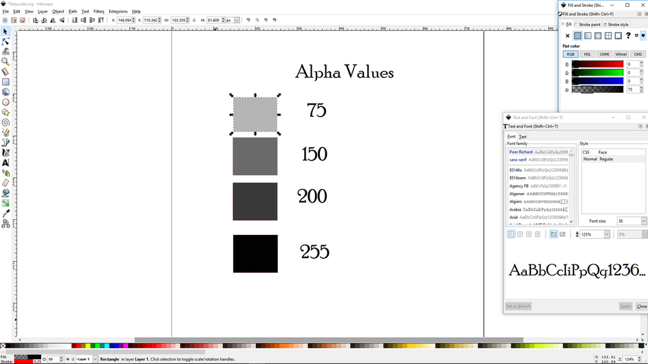
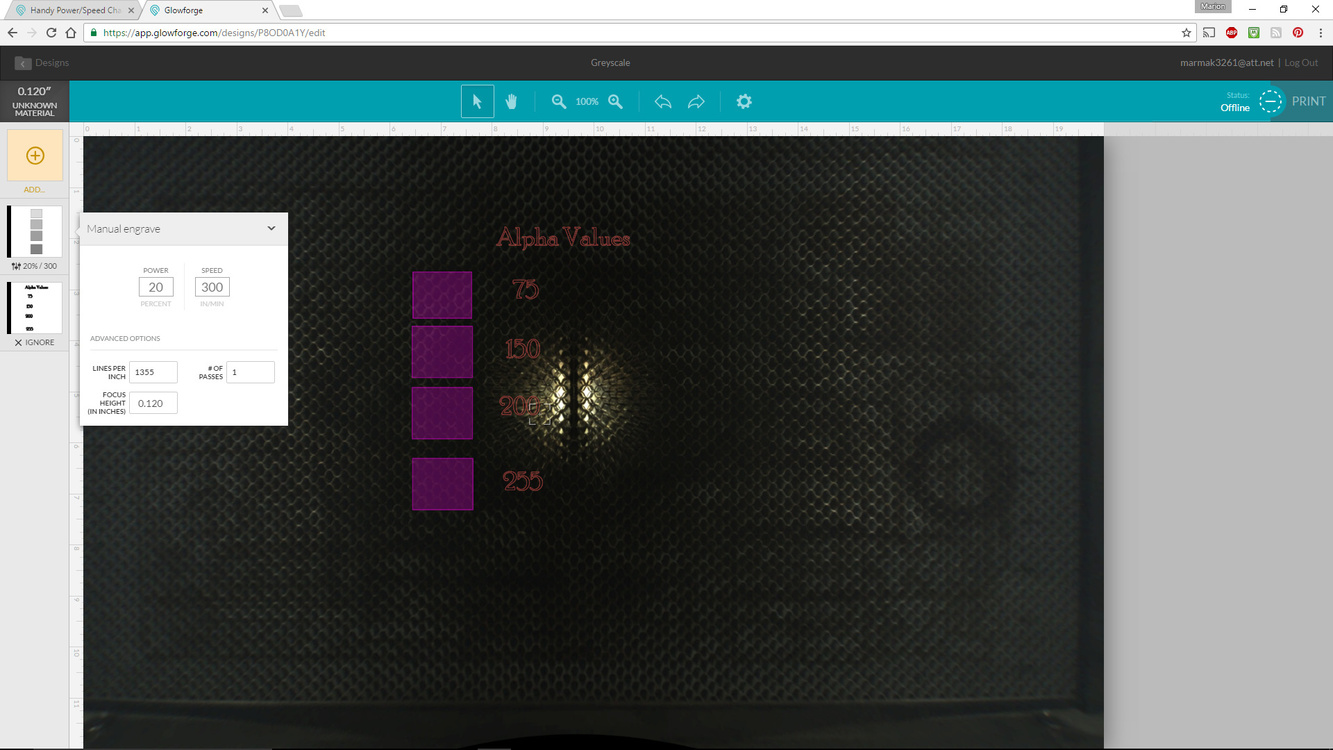
By the way, here is a test for different Alpha values Inkscape Screenshot and then Glowforge workspace. Don’t have the greyscale enabled for me at this time. Unless I am missing something, which is very possible. Note they are all treated as one operation. Note I had to convert text to path to have the letters and numbers import at this time.
Would greyscale just be setting RGB to all the same value from 0 to 255? Like 50% greyscale would be 127 in R, 127 in G, and 127 in B? That would be my assumption instead of using the alpha values.
The CAM software is LaserCut 6.1 (or a LaserDRW plugin for Corel on the K40). I design using AI, Corel and Inkscape. Corel is my “go to software” but I teach using Inkscape so I don’t have to worry about what the students have or can/can’t afford.
These engrave when a line color is specified as an Engrave function. The line has to be a fully bound shape (closed - no open lines) and the laser engraves everything contained in that shape. So an outlined box would be fully engraved. But if I embed another shape inside the box, it will engrave up to the embedded shape. That would then leave the embedded shape as unengraved and raised. If I want the embedded shaped engraved then I make the box outline a light scoring cut instead or I make an offset smaller box to perhaps engrave a thick border around the embedded engrave.
It’s an exercise is positive & negative space when designing.
[quote=“Christopher, post:11, topic:4358”]
RGB to all the same value from 0 to 255
[/quote]
At this point in time it makes no difference what number of RGB nor alpha, all fills are engraved at the same settings for each square I designate separately. So the workspace import sees a fill and just treats it as a generic fill at this point and then you can say how dark and what resolution each is. A black square can be a grey engrave and vice versa.
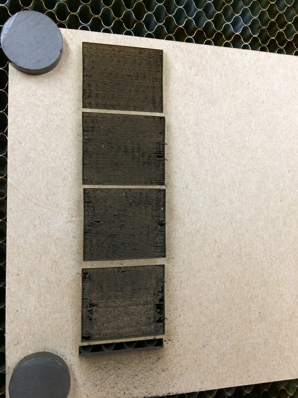
More fun on this later on. I just engraved the four squares with different alpha values in Inkscape. They all were engraved the same in the Glowforge, as I expected.
You can customize your settings as you wish. The laser will do what you want. It’s just that the setup is in the operations settings in the workspace and not in the design file.
It sees a fill, then you decide what shading it gets be changing the power and speed at which it does the engraving.
Though if you exported the drawing as a .jpg or .png of different colored squares, then you’d get different results because then it would apply the greyscale because it would be a picture import instead of a vector input?
Ahh OK, this makes sense. It’s more or less just a design import but the GF interface doesnt recognize (or associate) the color setup in the original design to specific tasks. That step is done manually in the GF software. Got it.
Finally found them there magnets. Little package was hiding.
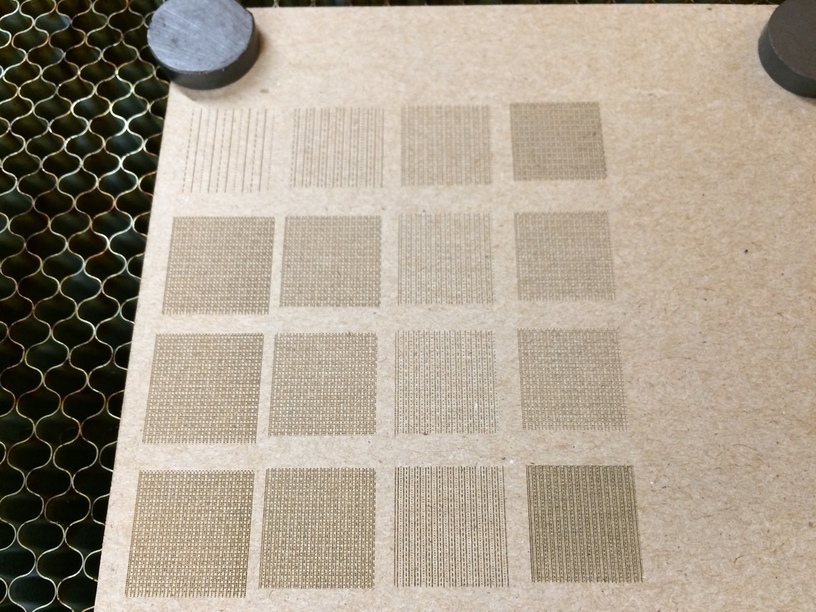
I know folks like puzzles. Here is a set of squares that are not labeled. Each has a distinct set of 3 parameters. I changed only one parameter per square. At least I think. This was just an early version to get familiar with the UI and not care about results. Kept it very light.
This is chip board. Works good.
Also, I did some close scoring on chipboard and it had some embers around the cutting point but no fire. Very good air assist and exhaust.
Testing out 0.18" walnut that I prepped myself from some slats I had. 80% power 15in/min goes through without masking perfectly. One cut. Will try other settings such as lower power faster two cuts.