So I’m trying to determine the “intricacy” limits using varying materials - I have some projects that are going to focus on extremely fine details.
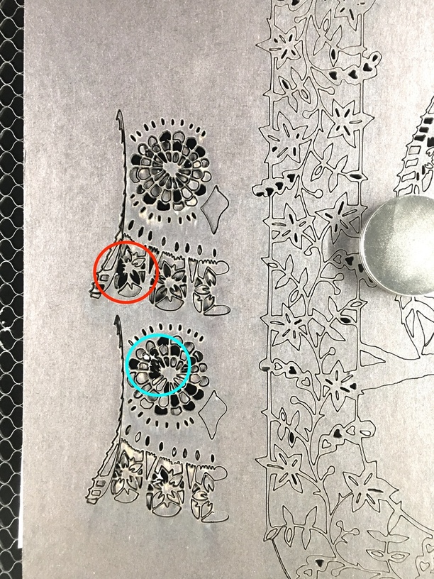
Here’s a close-up of a sample I’m working on. Here’s where I’m confused - top sample was cut at 400/full (pro), bottom at 500/full.
At the slower speed, some intricate details burned up the material, but at the higher speed, those sections were fine, but a different section was vaporized.
I have a theory - that the amount of time it takes for the beam to re-visit an area, or time the material has to lose some of the heat from the previous pass, is causing different “burn” results. So I’m posting here for thoughts/opinions.
For reference, the magnets are around the size of a quarter ($0.25), and the fine details I’m losing are (supposed to be) <0.5mm.
Speed is affected by the shape of the line – even if you have it set at 500, it’s going to have to slow down to go around a small circle, so you’re going to get a bigger burn.
I don’t have any suggestions, since I’m still wrapping my own brain around these concepts, but maybe someone more experienced can offer something to try!
If you want intricacy, take it off of full power is my advice and set it to 100.
And probably less than 100. The speed isn’t constant. It has accel and decel states to get around things. So your best bet at a consistent cut is something that has consistent speed, which means lowering the speed and subsequently lowering the power to modulate the energy delivered.
Rather than burning up your material with a cut that fancy, (which will take a long time and introduce other variables such as line shape), you can get a quick understanding of the relationship between power and speed using something like these on a sample of your material.
(Just makes it easy to quickly determine the best settings for a particular material.)
I shared those files last year about this time, but they are not set to engrave for the currently used scale. Still, if you want to rework the engravings for the current scale, you’re welcome to modify it.
Those little squiggle shapes are there for a reason, the machine reacts differently on tightly curved lines than it does on straight cuts, due to acceleration/deceleration forces on the head and gantry. You have to account for them by slowing the cut down a few points on tightly curved cuts, and that’s going to impact thin bridges between the material. So I like to use those to test unknown materials to make sure the settings I choose can handle tight curves.
Anyway, run one of those at fastest speed, see the results you get, then cut the speed in half on all of the cuts, and see what results you get. It’s a quick iteration to get to the correct answer for any material.
Huh! I see I got side tracked into working on engraving and didn’t share the cut template…let me see if I still have it.
So I used test prints with that file to determine a starting point for my project. I feel like that’s a good approach, but then I run in to this apparently “conflicting” situation…
I tried with two passes, at 75%, did not cut thru in some places, but vaporized the details in others…
Problem here might be the need to do a negative adjustment for kerf.
The bridges between the cutouts are what you are trying to preserve in this design, not the actual shapes you are cutting out. So you might need to do a negative kerf adjustment on the cuts to make them smaller.
You might lose some of the tiny details, but that design itself might be banging up against the physical limitations of the beam size.
I get what you’re saying, and would agree - that’s what I started out trying to figure out - but that would not explain why details that are being kept at a lower speed suddenly get blasted into the next dimension at a 25% higher speed!
I have used the slower speed and power with more passes and if the design has a lot of quick turns it is my guess that the head jumps whatever the setup to keep from destroying the head when it hits something, unless the speed is really slow and then it might take much less power but a very long cutting time.
One thing I have done is to go through and take out sharp corners wherever possible.
The speed we set is a maximum, not a minimum. As others have said, the motion profile of the laser head includes consideration for acceleration and deceleration and as a result the actual speed is constantly changing.
The slower you go, though, the less delta there will be from the fastest the laser moves (which will tend to be longer/straighter lines) vs. the slowest it moves (which will tend to be in areas approaching corners or in tightly radiused curves).
The problem is that we all want our cutters to cut as fast as possible so the inclination is to try higher speeds with higher power. But for cuts where you need the speed*power to vary the least amount, going slower with less power is likely to work better.
Having said all that, in the interests of fair disclosure, I have only owned a laser cutter for a couple of months so I’m a relative neophyte. However, I have been doing CNC machining for many, many years. The factors you need to consider in CNC machining in order to keep the “tool speed” the same as the CNC accelerates and decelerates are common to all motion control systems including the one in our GlowForges.
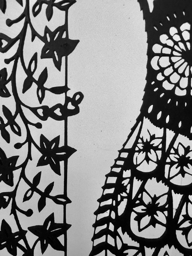
Thank you - it makes sense, and based on earlier comments, I decided to drop it down to 1/3 speed (150) and although my test samples from the graphic showed 150/50 to be sufficient, I bumped it up to 65% and added masking to the back side to prevent too much flashback.
It took, obviously, longer to cut, but the result is quite satisfactory. I think using a backing board instead of masking would be better still, because some damage was done removing the masking.
Here’s a close-up of a similar section I posted originally, this is the actual cut chipboard, in black - I adjusted levels to give the clearest view using my laptop display as a light table…