I had that figured out at one point …something about a clock… dang! It’s totally gone now.
Nope…found it… ![]()
This describes how you can use the Basic machines to get up to…I think it was 18 inches or so, by using an indexing mark.
In that case, working with a circle of pre-cut wood, the indexing mark was the center of the circle. Since you are going to be cutting a circle out, you can actually just use two lines outside of the circle at the halfway point.
In your case, you can adapt that to cut a 12" circle fairly easily…but there’s one catch…you need to start with perfectly square base material, so cutting a 14" by 14" square should do and will give you a little leeway. (Downside to the Basics/Plusses…you can feed it in with a Pro.) I wouldn’t try for the perfection that a 12" x 12" piece of material would require…it just adds additional error potential, and forces you to place the indexing marks inside the circle.
Another couple of things you’ll need to do…make sure you have run the Camera Calibration, and use the Set Focus on the center of the material to start out with to make sure you have enough space to work with.
You are going to need to make sure it stays perfectly perpendicular…so use the boots and anchor against the side of the tray. (Also cut a couple of straight jig spacer sticks to use against the side and front. They are useful for a lot of things…this is just one of them. I use them all the time to square things up…they’re a very simple form of jig.)
Okay so after you have made your preparations:
Mark the center of your material on the masking so you can approximately align the center of the “circle” there.
Create a simple file. It will have exactly half of a 12" circle as a red cutline, with two indexing marks aligned exactly to the end points of the semi-circle, in black. (Matter of fact…I’ll load one below that you can use.)
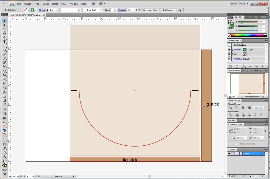
I’ve got a sketch of what’s going to happen below:
-
The white background represents the 12" x 20" bed.
-
Tape one of the jig sticks to the side of the tray along the right side. (It’s nothing more than a spacer and an anchor for your material.) You will place the material (light brown square) flush against that jig stick. (And if you have masking that hangs over the edge of the material - trim it off so that it doesn’t get in the way. It has to be perfectly flush.)
-
Do the same thing with a narrow jig stick across the front of the machine. Anchor it with some tape.
-
Once the material is squared up, which the jigs help with, open your SVG file in the interface.
-
Use the Set Focus on the mark on the centerpoint you drew on the material. (It’s not going to be in the center of the bed.)
-
Select all (CTRL+A) and align the design so that the center mark on the semicircle appears to be right over the center mark on the material on the screen. Use the arrow keys on the keyboard to shift the entire design, do not try to drag it. (Too easy to accidentally resize, rotate or shift something.)
-
Set the Center Mark (green) in the design to Ignore. (It’s just for getting the circle near the center on the material.)
-
Process the Black index marks as a light Score, and send the Red semi-circle to be Cut.
-
Open the lid and rotate the sheet of material 180° without shifting the spacer sticks. Seat the material flush into the cradle created by the jigs.
-
Set the Cut to Ignore. (Do not move the design on the screen, just click the thumbnail column.)
-
Print the Score marks again. If they do not align perfectly over the previously scored marks, you will need to select everything on the screen (CTRL+A) and use the keyboard arrow keys to nudge the whole design in the correct direction and score again until those lines land exactly on top of the original scored lines. (By using the two jig sticks they are going to be pretty close, but if your square material isn’t perfectly square, it can be slightly off. And for this part, I like to watch the action from right over the top of the machine to make sure they hit where they are supposed to.)
When I say the marks have to align on top of each other perfectly, I’m talking about the actual lasered results on the board - not what the screen is showing. So you have to watch the actual lasering being done…do not look at the screen and think that is where things are going to line up. (Ignore the screen, look at the actual results. Each time, if it takes more than one time. Don’t shift the design on the screen except as a whole using the arrow keys, and only if you need to do additional testing.)
- Once you have seen that the lasered marks are landing right on top of the originals, you can set the red semi-circle to Cut and it will finish the circle.
That ought to get you close enough that a little sandpaper will smooth out any rough edges. ![]()
And let me know if it works for you…I didn’t actually run the test on it, but the spacer jigs ought to help with the alignment quite a bit.
circle.zip (634 Bytes)