Since people have been concerned about tube replacement, I thought some would be interested in an example step-by-step of how a competitive product (Full Spectrum Laser) goes through the process.
The actual steps for Glowforge will differ in a number of ways for many reasons, but if you feel you’re mechanically challenged and uncomfortable with the types of steps they show, this might be an indication you will need to seek assistance when the time comes with your Glowforge.
Well, I admire them for such a detailed video - but what a faff!
I imagine that the GF tube won’t be half as fiddly to replace, as it is readily available just by lifting the lid.
It’s used for the dielectric and insulation properties in high frequency signals, such as lasers and microwave. Other plastics used for insulators, like those used in common electrical tape, would actually retain a charge that messes with the signal.
Not to mention the connectors on the tube are nearly impossible to solder directly to. We spent a LONG time not wanting to use the “Wrap wire and tape, call it good enough” method, because everything I know about electrical work screamed for me to find another approach.
Most other directions I have seen about wiring for a tube have you put caulking on, instead of silicone sealant. But it sure looks like that is just another name for the same thing. A quick google search says the only difference between them is elasticity.
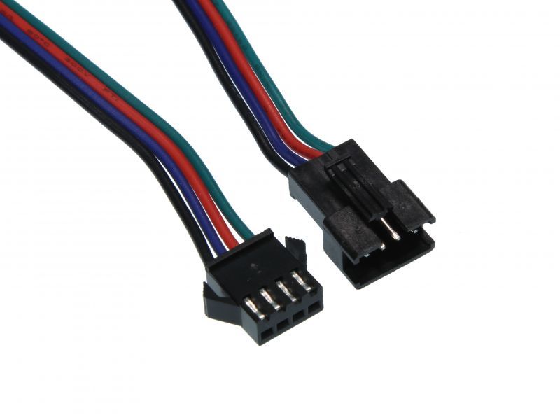
The main things Glowforge can do to make the replacement process easier would be to send out tubes with the wires for power and ground already connected. Then you just pop the lid open, disconnect the two wires on the old tube, disconnect whatever holds it to the gantry, swap out, secure new one to gantry, plug in 2 wires. Done.
If you watch the video, that essentially is what they have on the opposite end of the large red power cable. The main issue is the connection at the tube.
Most existing glass tube lasers consider the cable a reusable component, and leave it to the user to attach the cable to the tube. Which (for new users or the plain clumsy) can lead to broken tubes quite easily.
If Glowforge just considers the cable to be disposable along with the tube, that adds some cost to tube replacement, but removes some difficulty in exchange.
How and where would other plastics store a charge?
I suspect the only reason they use PTFE tape is that it’s very malleable and you can effectively do a very fine wrap around the terminal. Try wrapping something like that with electrical tape without breaking it.
I suppose it could also be possible to get some corona around those terminals without the PTFE. The voltage terminal to terminal isn’t super high but combined with a LF pulsed output and those sharp, pointy terminals you might see something PTFE would be beneficial in this case too since it can be finely wrapped without leaving voids and gaps (unlike electrical tape)
I doubt there’s anything special about the power supply output “signal”, and certainly nothing that the insulation would effect. Maybe @aeva will chime in
Sounds like you haven’t done much work with electronics and dealt with electrostatic discharge.
Paragraph 1: Static electricity.
P2: If you Google it, you’ll find there’s reasons for everything. It’s definitely because of the insulation and rated properties of the plastic. Standard electrical tape is only rated up to 600V and 105c/220f. Bonus info: different coloured tape indicates different power phases to electricians.
P3: (no comment)
P4: Well, call it what you want… Signal, anode/cathode lead, driver lead. But it has to reliably charge and discharge the high voltage in order to maintain timing with the head motion so it can project a cohesive image. In that regard, the insulation can have a capacitive (as in: store excess charge) effect that will blur imaging.
Or hey, the vinyl tape used in standard electrical tape can smolder from the high voltage, gasses can enter the hopper chamber, combine with CO2 lasing, emit toxic gases… no big deal.
Exactly how and where would a static charge be deposited using PVC or rubber insulation and not using PTFE?
If you Google it, you’ll find there’s reasons for everything. It’s definitely because of the insulation and rated properties of the plastic
You’ll definitely have a solid reference for that then. Maybe a commercial application note describing failure modes caused by the use of something other than PTFE to insulate your leads and terminals
Electrical tape is 600V per wrap, by the way. Teflon tape is about 1kV per wrap. Neither are sufficient for insulating CO2 laser terminals, but because Teflon tape is so malleable you can easily use multiple wraps. Again, try doing that with any other insulating tape without damaging the terminal
But it has to reliably charge and discharge the high voltage in order to maintain timing with the head motion so it can project a cohesive image.
Sure. At what frequency? If we assumed the lead had a resistance of 1 ohm and the inter-lead capacitance is 500pF (which are ridiculously generous - actual values will be substantially lower) then the power supply can make use of frequency components up to 320MHz before you’ll see any distortion.
According to Sam's Laser FAQ - Carbon Dioxide Lasers under “Electrical Modulation of a CO2 Laser” the laser itself will filter out any pulsing above a few kHz. I.e. above a few kHz, you will get a CW output regardless of the input.
Even if “capacitance” was a problem, what part of it will be effected by the terminal insulation?
You have:
Capacitance between the two leads, which is substantial but entirely unaffected by the insulation on the terminals
Capacitance between the two terminals which is entirely unsubstantial (very close to 0pF)
Capacitance between the HV terminal and ground which is entirely unsubstantial (very close to 0pF)
Wrapping the terminal with PTFE rather than PVC will have no substantial effect on a capacitance that was not substantial to begin with
For the most part, plastics will be insulators rather than retain a charge. Most static electricity is the result of friction or stripping of electrons (such as ripping tape off a surface). It’s called the Tribolectric effect.
Different materials exhibit different potentials to retain charges on their surface.
Granted, as a wrap, there’s not much chance of friction. If you actually Googled for a table of potential energy, you’d find that Teflon is for all practical purposes at the bottom of the list of all other plastics. Check out https://www.trifield.com/content/tribo-electric-series/ if you must.
If you want more exact details than that, I don’t have the patience for it.
Yes. Like putting on two coats provides double the insulation on a cold day. Except that’s a bad analogy based on the laws of thermodynamics and totally unrelated. But that’s also not important right now.
The real question is how much padding and stress you want to put onto a tenuous connection to a glass tube that, once snapped off, is likely unfixable short of replacing the tube.
I’m not going to engage in a long discussion about how much charge a material can hold when the key takeaways of using teflon are:
It’s thin for such delicate connections
It’s best for high frequency and high voltages “per wrap”
I can think of at least three inventions off the top of my head that were directed specifically at making tube installation simple. I can assure you it has next to nothing in common with that video, and requires exactly no plumbers’ tape.
Then perhaps you can clearly summarize what you’re arguing about, because honestly, I read your replies to my responses and all I see is you being offended at me answering your questions or you and I agreeing on various details. Your ego obviously wants me to say I’m wrong about something, so articulate it and let’s get on with our lives.
I appreciate the exchange between @sam and @dan_berry. I felt that there was some strong energy connected to the posts as they developed, but couldn’t jump back in to allow the knowledge shared to come across stronger than the personality and energy of the posters. As an early participant in the question of using teflon tape, I am amazed at how this developed. I just don’t know enough about the physics involved to negotiate. I am intrigued though about the role static electricity and electrical capacitance play in tape. I naively assumed that an insulator was and insulator, case closed. Although I do recall the role cello tape played in making molecular thin carbon nanotubes and wanted to try this out. I am very edified by the whole discussion of electrical wires and the connection challenges to laser tubes and power supplies. And the whole mechanical issue of how to make good connections. I’m sure that the Glowforge will make this whole challenge easier for the consumer. Perhaps it would help to focus on the specific application on this particular laser and their recommended practices on the connection issue. This thread is about replacing a C02 laser and its challenges. Perhaps more illustrations of the varied ways this happens and why certain practices are recommended might assist us all in getting more familiar with the challenges we might face, or the problems the Glowforge will eliminate?

 I would never have thought about using it for electrical connections.