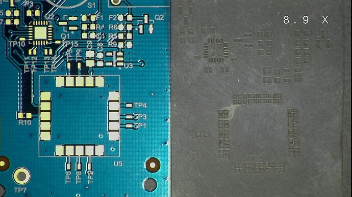
How to create a PCB stencil

If you make your own surface-mount printed circuit boards, then one thing you’d have to do is send out your Gerber files to have a shop like OSH Stencils create a PCB stencil for you. While these have come down in price a lot in the last couple of years, you still have to wait quite a while to get the stencil back in the mail. But if you have a Glowforge then creating your own PCB stencil is easy!

This quick tutorial will walk you through creating your own PCB stencil. It assumes you’re using Eagle (free version is OK) for your board design. Other CAD tools could be used as long as there is a way to output an SVG file from selected board layers.

For material, you need 2 things:

  1. 4 mil (0.004") mylar sheets, approximately 8.5 x 11"
  1. 110 lb card stock paper, 8.5 x 11"
  • available just about anywhere office supplies are sold. I got mine at Walmart.

We’ll be using Eagle, Inkscape, and the app.glowforge.com web app.

Here’s the process:

  1. In Eagle:
  • In the Layers Tool in BRD view
  • Deselect all layers
    • Select 20 (Dimension)
    • This is for reference only - it will be deleted in Inkscape
    • Optionally, you can skip selecting this layer if you don’t need to see the board outline in the SVG file
  • Double-click on 31 (tCream) to edit
    • Choose the solid pattern (no stippling)
    • Pick a color, such as Green
    • Select 32 (bCream) instead if you’re making a stencil for the bottom layer
  • Select 31 (or 32)
    • Layers 20 (optional) and 31 or 32 are the only visible layers at this point
  • Still in BRD view, run eagle2svg ULP
  1. Open saved SVG file in Inkscape
  • Create cutlines for the stencil outside the dimension line and choose a color (different from the stencil cutouts (pads))
    • Note: do not use black for ANY object
    • Note: do not cut all the way around the stencil or the fan will blow it off the bed
    • Use guides to ensure alignment of cutlines
    • You can avoid cutlines by cutting the mylar sheet to the desired size in advance
      • In this case, omit layer 20 when exporting
  • Add any text or labeling and choose a (different) color
    • Select text and run Path>Object to Path
  • Ungroup the stencil elements that were grouped by eagle2svg
    • Continue to ungroup until all elements are separate objects
    • Delete the dotted line (dimension) around the stencil objects if present
  • Save the file
  1. Place a sheet of 110 lb card stock under a 4mil mylar sheet and secure to the crumb tray with flat magnets at the corners
  • Card stock ensures the laser can focus properly and helps to keep the mylar flat and stable
  • You can also check the laser output by observing how deeply the laser cuts into the card stock “wasteboard” - it should not cut all the way though. If it does, reduce the laser power shown below
  1. In Glowforge app
  • Import SVG graphic and place it in the desired spot on the mylar sheet
  • Rearrange order of operations if needed
  • Use the following settings for each operation:
    • Stencil cutouts: Manual Engrave 650/45
      • We’re engraving the cutouts to burn them out rather than creating small pieces of mylar that will fly around the inside of the unit
    • Embossed text: Manual Engrave 650/15
    • Stencil outline (perimeter or cut-through lines): Manual Cut 500/45
  1. Select “unknown material” and a height of 0.01" (lowest allowed setting)
  2. Print

Enjoy!

19 Likes

Once you have the stencil, are you using solder paste, photo etch or what process to create the PCB?

Lead-free solder paste.

I 3D printed a set of jigs that I tape down to a silicone mat and then tape the stencil to the top of the jigs before spreading out the paste. Depending on the complexity of the board, I will either use the air gun from my rework station or run it thorough the reflow oven to mount the components.

Rob

1 Like

Cool, thanks for the info.

Excellent Instructions!!! This worked like a charm. Saved me TONS of experimentation.

Thank you so much for sharing such a detailed explanation.

Results:

https://www.instagram.com/p/Beg7_P1DD2U/?taken-by=bpcmusic

1 Like

Cool! Glad it worked out for you.

1 Like

Thanks for the step by step, great to see others making pcb stencils!

I would like to contribute my slightly different method that seems to work for my setup.
I use Altium designer rather than Eagle for PCB, and surprisingly it does not have an easy way to output a vectored file from a gerber (at least that I have found). I think this may work for just about any gerber viewer though.

‘Print to PDF’ from whatever program you are using to generate or view the gerber of the paste mask layer, and be sure to use the option to scale the image to 1:1, do not use ‘fit to page’ or similar.

In the Glowforge app you can import the .PDF file directly. Clean up any extra text or features that is not wanted. Change the process pass to a ‘manual cut’

Settings I use for the cut is: speed = 500, power = 16, height = 0.01" , “unknown material” (I do not have the pro Glowforge)

Prepare the mylar between to wet sheets of standard printer paper. I saw this first from a video at: https://www.youtube.com/watch?v=WlvlHMxde3A
The wet paper pulls heat away from the mylar and allows for some pretty clean lines, works great.
Running on card stock beneath the layers would be a good idea too… I have not tried it yet but may help prevent small pieces floating around.

The stencil in the attached image took around 1 minute 35 sec to process.

3 Likes

David,

Good to see a different approach.

In my process, I use card stock underneath as a “waste board” and engrave the openings rather than cutting them out. This prevents the problem of small pieces of mylar (and/or paper) floating around the unit.

I’ve never had an issue with the openings being coarse, but I will try your “wet” process to see if that improves the results.

BTW, I started with a PDF-based import process also, but abandoned it once I found the Eagle extension to export SVG files directly. Even with 1:1 print settings, I have had issues with unwanted scaling when exporting PDFs (e.g. Sketchup) so I had more faith
in this approach. I probably just need to experiment more with the PDF process as that path gives you more flexibility wrt importing files form different applications.

Thanks for the post.

BTW, where do you get your boards fabricated?

1 Like

I’ll try the engrave method as well with the Glowforge… I had tried it on a different laser system we have and never got the settings to work that well, but would be good to re-try.
And I agree that not all PDF outputs are 1:1, I have fought with that before as well.

For the PCB fabs, I have recently been using pcbway.com … they have some pretty low prices if you are willing to wait a couple of weeks for them and need more than just a couple of boards. However I have had stuff show up in little as 5 days (to Texas, US) when selecting their 24hour turn.
AND they have some crazy low prices on making metal stencils (~$30 total on average)…
So if I will be building multiple at a time, I will get the PCB in a panel and the stencil to go along with it. Other times for the occasional 1-off either from them or if I route my own PCB, I will take the DIY approach to the stencil.

1 Like