Hello fellow forgers! I hope those of you with your lasers are happily cutting away. I have a bit of a challenge here. I’m making a square picture frame. In order to optimize material usage, I don’t want to cut the frame as one continuous piece; I’d rather break it into four segments that can be assembled into a square. And I’d like those segments to be identical, so that any piece can fit in any one of the four positions. The problem is, I don’t know how to create that kind of uniformity in Inkscape or Illustrator.
If I do it by hand, things are inevitably just a bit off. I can free-hand a “jigsaw-fit” connection and copy that three times, so that the shape of the interface between the pieces is the same. But getting those to be positioned exactly in the right spot so that all four pieces match is beyond my abilities at this point.
Here’s an example. In this case, I only divided the frame into two pieces just to save time and to illustrate what I’m trying to accomplish. Any ideas?
Thanks!
I’ll second not being quite able to understand the problem. I think I get the gist of it, but maybe you could highlight specifically what doesn’t match up, as I can think of at least three guesses for what you’re saying, off the top of my head. I’m sure there are other interpretations as well:
You’re drawing the “innie” and “outie” parts of the connection separately, so they don’t match up
You’re positioning the connection by hand, and it might not be in exactly the middle, so it doesn’t match up with the other side
You’re drawing each of them individually, so they don’t match up
You’re ok making one “corner piece” and copying and pasting it three times, but that doesn’t get the finished square to come out the size you want
You’re having a problem with kerf
All of these have solutions, but it’s not clear right now what the problem actually is.
Thanks guys. I knew I was going to have trouble explaining it! Chris, you’re on track with suggestion 2. Unless the interface is right in the center (width) of each piece, they would not be interchangeable. That’s one problem.
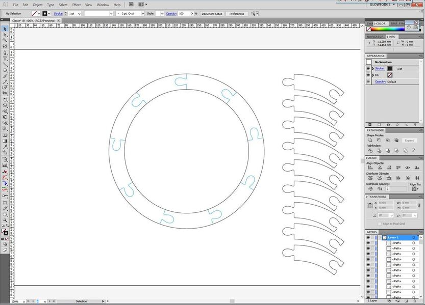
The other problem is this. And perhaps a square isn’t a good example, because in this case I was able to align the connections with the automatically appearing “snap” guides in illustrator that indicate the halfway point or center of an object. But let’s say this frame was circular and I wanted to cut it in 9 pieces. How would I get 9 exactly identical segments, with the “puzzle connection” centered on the ends of each one? Ideally I’d have one piece that I could cut 100 of, and any given 9 would snap together to make a circle.
For a circle, you would need to use the rotation tool to rotate the parts through the correct angle (360°/9) before copying and attaching the parts using the join function. (And you’d only have to make one and then copy it.)
As long as you draw only one open path for the “puzzle” connection, and use a copy of that path for all connections, it shouldn’t matter if the “tab” portion is exactly centered, because all of them are copied from identical patterns so they will always line up by default.
In Inkscape, I have never found a good solution. That is one of the things I don’t like about “art” programs. ai may have a bit more but I don’t use it so I’m not much help.
I hate to be the guy that has a hammer and sees everything as a nail but this would be a piece of cake in Fusion 360. Just lay down some center point construction lines and go to town. You could probably do the same in Inkscape now that I think about it. Just lay down some lines to mark the center and then delete them when you have everything layed up.
The trick to using inkscape as CAD on the cheap is guides and turning off strokes.
If you double click a guide it will open a dialog that allows you to type in its X Y placement and even define angle it sits at.
Strokes can be useful for kerf compensation (@Jules made a nice tutorial on the subject) , but they will get in the way of accurately sizing objects. A 2 x 2 square with a .030 stroke will measure as 2.030 x 2.030 when you select it as an object. This can really throw things off. Only use filled objects without strokes unless you design requires open curves, but that’s a different story.
Here is an example .SVG. The layers names try to identify what the different layers and shapes are used for. It’s by no means a comprehensive tutorial, but maybe it can give you some ideas.
That’s a great point you make. You can use the coordinates and dimensions to get exact lines. As @mike10 says, guides and grids also work. Then booleans. I thought a lot about this when I was designing the compass rose. It has only a few pieces that are just flipped or copied to make it up. My conclusion was to use OnShape, but I was able to learn a lot about how to make accurately dimensioned parts in Inkscape. Make sure you set preferences to measure object size from center of the stroke.
@marmak3261, can you recall where that setting is in the inkscape preferences? I can’t seem to find it.
-----EDIT-----
Found It! It’s not well labelled. Preferences->Tools->Bounding box to use->Geometric bounding box -----EDIT-----
Another helpful tip:
If you use your stroke for kerf compensation make sure to uncheck “Scale stroke width” (Preferences->Behavior->Transforms->Scale stroke width) to prevent your strokes from unexpectedly changing on you.
I think you have a misconception about your so called “art” programs. Illustrator, and even Photoshop, are every bit as precise as any Autodesk program.
Yes, you can do this in just about every “art” program I can think of.
I won’t disagree with the precision, I’ll just say that for me, getting there is MUCH easier in Fusions sketches than in either Inkscape or Corel. This may well be a thing about paradigms and how my head works though.
Great suggestions everyone, thanks! @mike10 and @jules, thanks for putting together those examples. They helped me figure out how to gain some uniformity.


 can’t speak for Inkscape or Corel - Illustrator is my go to for layout even though I have just about every CAD and 3D package at my disposal.