I started with this post: External Venting Solution Review
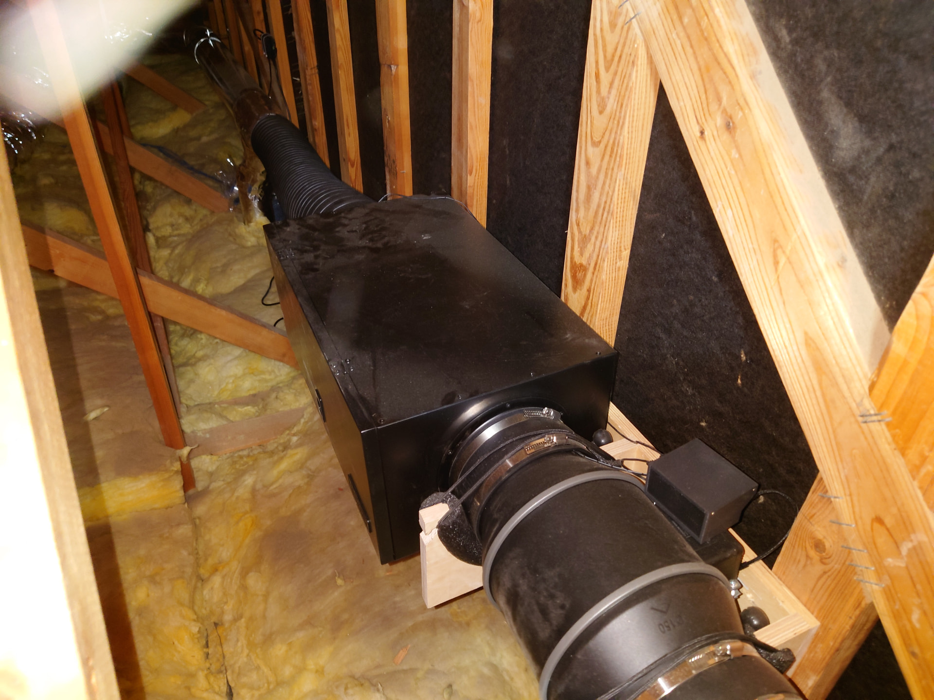
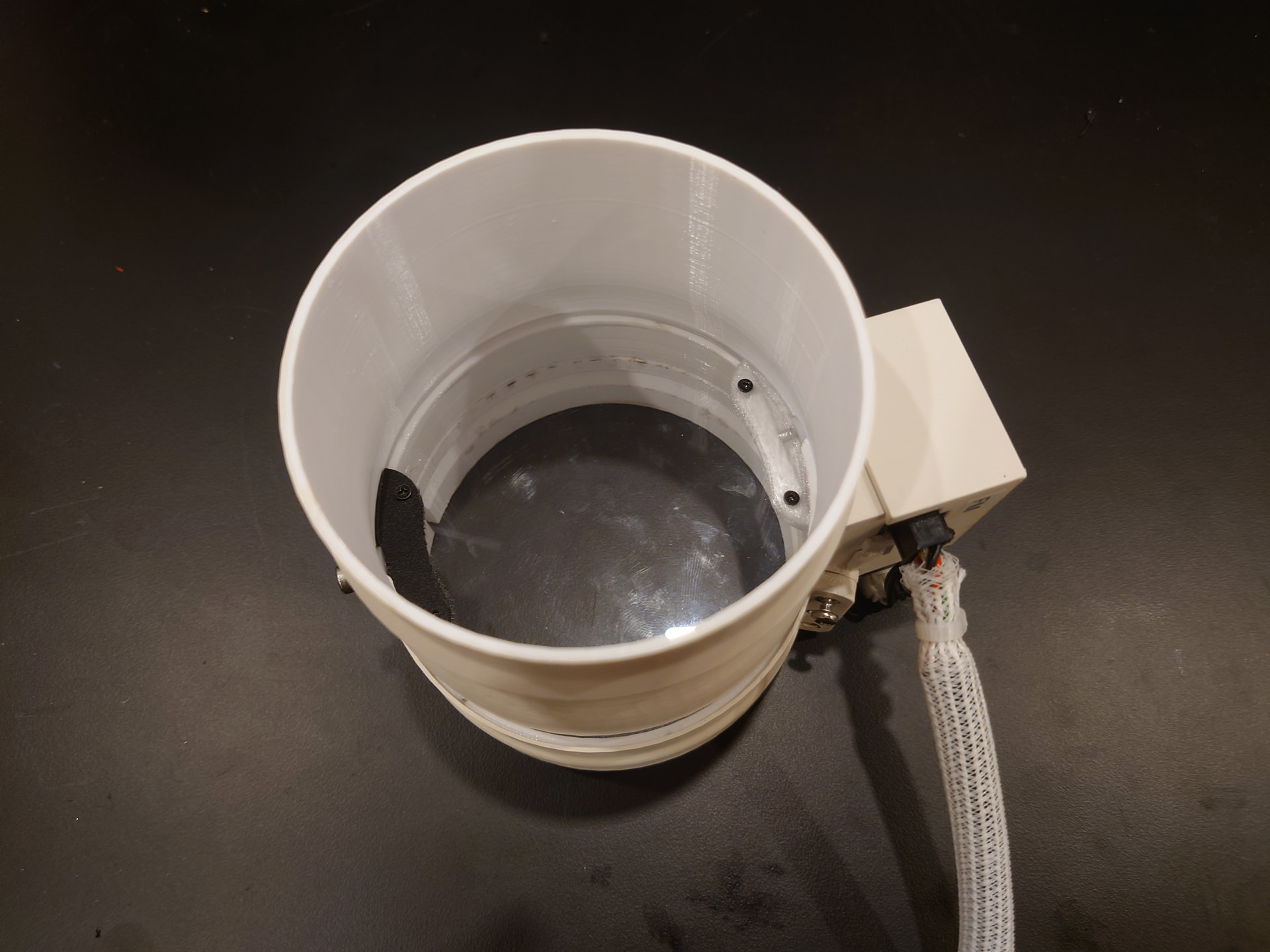
I finally finished. The system consists of an attic-mounted AC Infinity Cloudline S6 Pro inline fan with their 6 inch filter box. I probably should have gone with the 8-inch versions, but I didn’t realize the head loss would be as high as it is.
The fan pulls from four independently controlled inlets: the Glowforge, the fume extractor for my soldering station, and two ceiling mounted vents above my 3D printer stations. Each inlet has a custom-designed blast gate. The blast gates are wired in pairs to one of two control units and the fan is controlled by a third unit. Each of the four gates also has a device monitor unit that determines the power status of the corresponding device. All control units and monitor units report back to a central controller that handles communications and status. This allows fully automatic operation. When I turn on the Glowforge, the vent opens and the fan turns on to the programmed speed. When I turn off the Glowforge, the central controller starts a timer and when that timer expires the fan turns off and the vent closes. The 3D printers work in a similar fashion except that I am monitoring them in such a way that the closing timer is triggered by the end of the print so I don’t have to turn the printer off if I am running a bunch of prints and don’t get around to setting the next print up immediately. Starting the next print triggers the vent to open again.
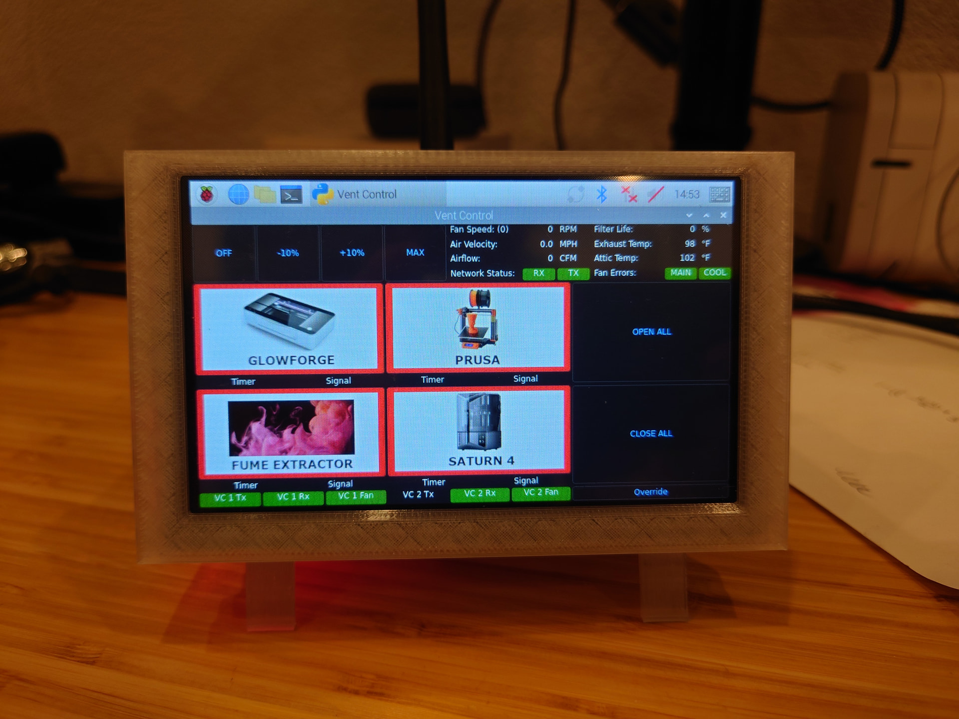
The central control unit runs on a Raspberry Pi 4 with a touchscreen and provides a GUI in addition to the automated functions, so I can override the automatic functions if I want and I can see the status of each of the remote nodes for troubleshooting. I programmed the interface in Python using PySide6 as the GUI framework.
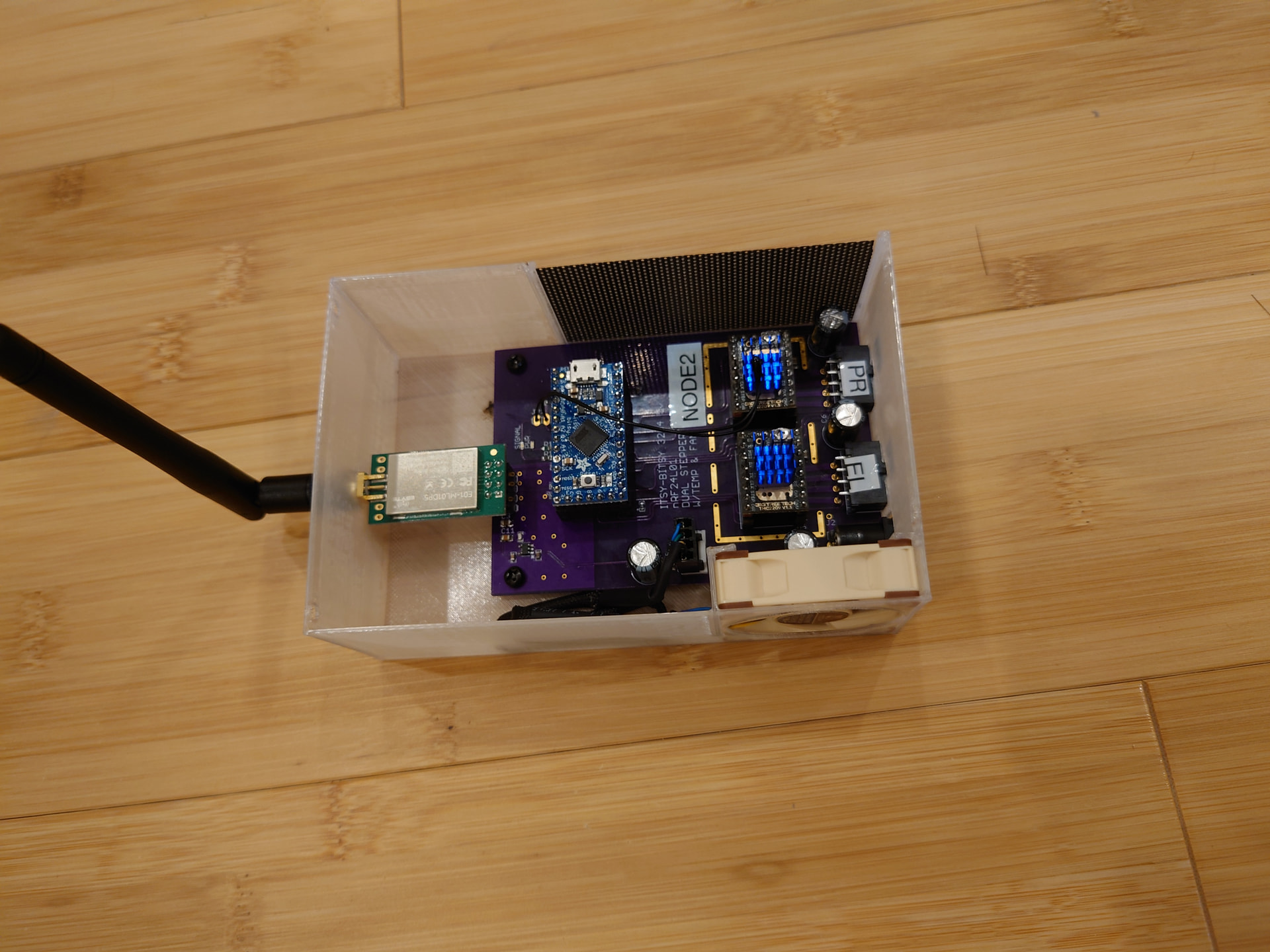
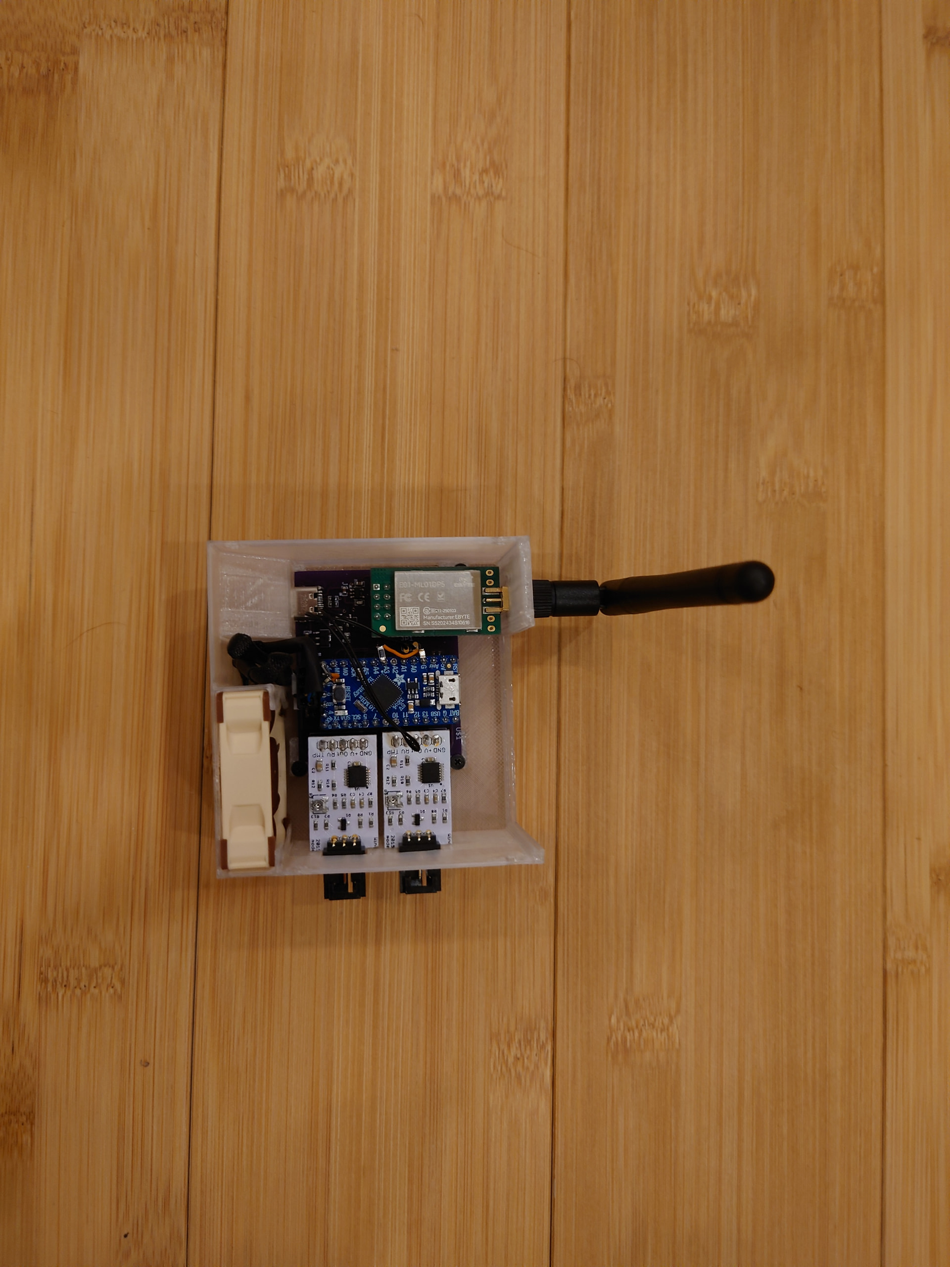
Everything communicates over an independent wireless connection using nRF24L01+ radios. Each control node runs from an ATMEL 32U4 processor on an Adafruit Itsy-Bitsy development board. The device monitor nodes run ATMEL SAMD21 processors on a Seeed Studios XAIO development board, since the device monitor nodes don’t need much IO and I wanted them to be relatively small.
One of the major challenges were that existing off-the-shelf blast gates are expensive and clunky. They take up a lot of space and aren’t all that reliable. I made my own by harvesting parts from some old 3D printers for the drive system and designing a housing that I could 3D print. I also used the Glowforge to cut the gates that close off the airflow from 1/8 acrylic scrap.
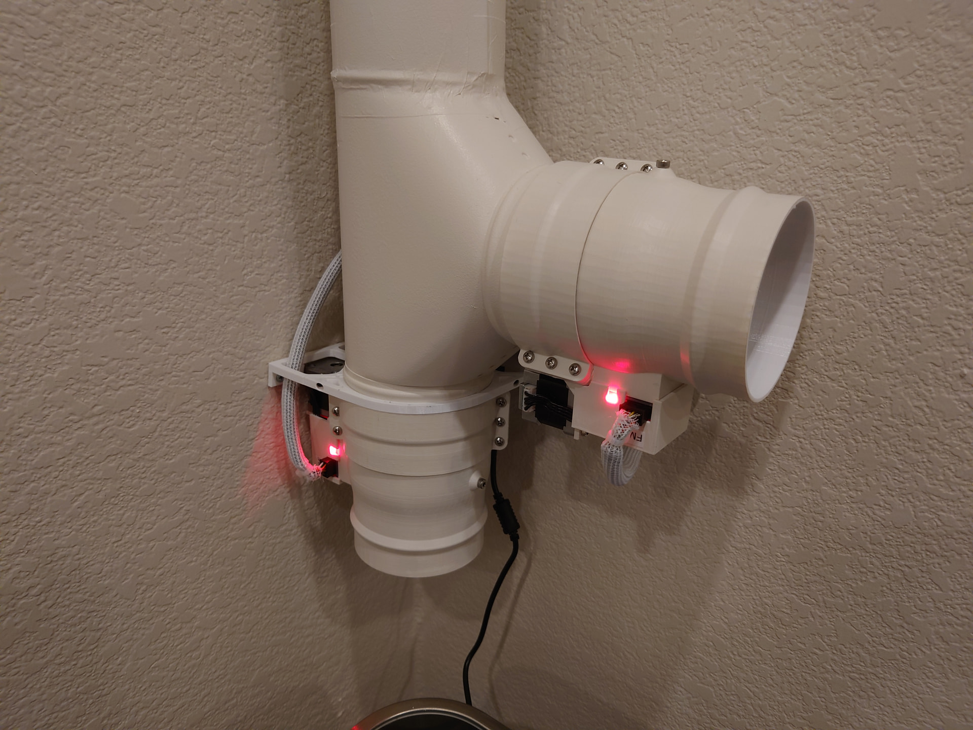
Two gates are in the office and are painted to match the walls. Two more are in the attic, mounted to rigid ductwork that feeds back to the fan.
The fan control unit reads and reports data from two hot-wire anemometer airflow sensors. These sensors are mounted in the airflow on either side of the filter box. By monitoring the airflow drop across the filter box I can get an idea of when I need to change the filter.
The inlet for the fume extractor connects to my workbench which has a 2 1/2 inch tube mounted along the back. A flex hose connects to the tube so I can move the fume extractor inlet around the bench and fold it up out of the way when I am not using it.
When the system is running at maximum speed I can hear it in the office, but it is much quieter than the built-in fan or the filter box. At 80% speed I can’t hear it in the office at all.
Due to the length of the ducting and the reductions from 6 inches to 4 inches, I get about 50% head loss, so the system maxes out at about 200 CFM as reported by the anemometers.
I’m happy to answer any questions or go into more detail if anyone wants additional information.