Here’s my approach to creating files for automated alignment using Snapmarks, when using the Pro pass-through slots. I used Inkscape but I am sure this technique would work with more advanced/expensive tools. ![]() You’ll need a basic understanding of working with paths and layers, as well as an understanding of how Snapmarks work - and hopefully a little practice using them. Of course, not everyone has this feature, and it’s no longer in development, but it works really well and I hope this will be useful while we still have them!
You’ll need a basic understanding of working with paths and layers, as well as an understanding of how Snapmarks work - and hopefully a little practice using them. Of course, not everyone has this feature, and it’s no longer in development, but it works really well and I hope this will be useful while we still have them!
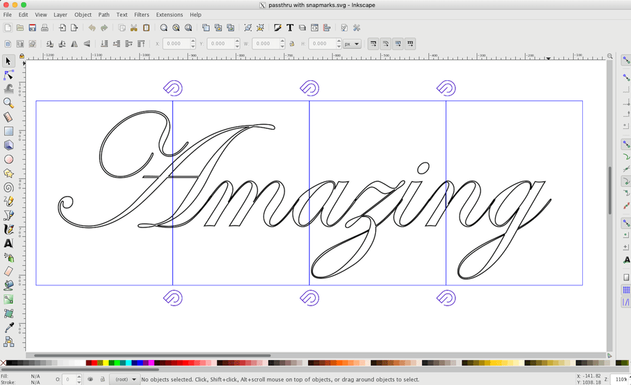
Create your design in a blank workspace on a single layer, to the final size you wish to print. This is critical, because the Snapmarks must be a precise size to be detected accurately. Your design will need to be in paths - so convert every object, including text, to path. Ungroup everything. Set no fill, and as many stroke colors as there will be different steps in the print process (i.e. different colors for cut and score.)
Draw a rectangle over one end of the design, ensuring it is smaller than the overall dimensions of the printable area of the bed. You need to leave about an inch/25mm of vertical space to ensure the Snapmarks can be detected (and scored) for each segment. The files we create will have two sets of Snapmarks - one at the top for alignment, and a second pair at the bottom which will be printed, providing alignment to the next section. It is critical that the rectangle and a set of Snapmarks on each side fit in the vertical dimension of the bed, as the files must not be resized in the UI later. Set no fill, and a different stroke color to the design elements. Copy this rectangle, carefully aligning the edges (each should snap precisely to the previous).
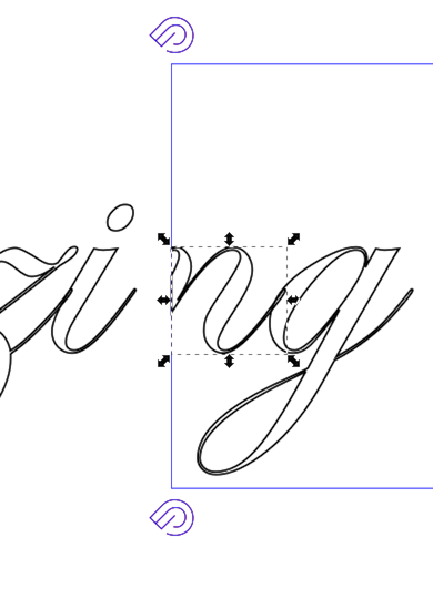
It is important to try and align the intersections so that they only bisect one object in the design, in this case, one letter in the text. You can likely move the design slightly to accomplish this. Note how the middle line in my example crosses the ‘a’ but just misses the ‘z’. It’s not obvious, but I also had to ensure next one didn’t cross the ‘i’ and ‘n’. It is possible to work around this if absolutely necessary, but I won’t include that in this post - perhaps later if anyone needs the information.
Add the Snapmark design (link) and duplicate it. Rotate so that they will be upright when the design is oriented as when being fed thru the machine, and locate one on each side so that the pair can be repeated without interfering with any of the design elements. Align (horizontally in my example), group them together, then copy and locate each pair so that they are near the intersection of a pair of rectangles. Select all of the Snapmark groups, align (vertically in my example), and verify they are not interfering with the design. Finally, in sequence, group two adjacent rectangles together, select that group plus the Snapmark group located near the intersection of those rectangles, align (horizontally in my example), then ungroup the rectangles.
You should end up with something like this:
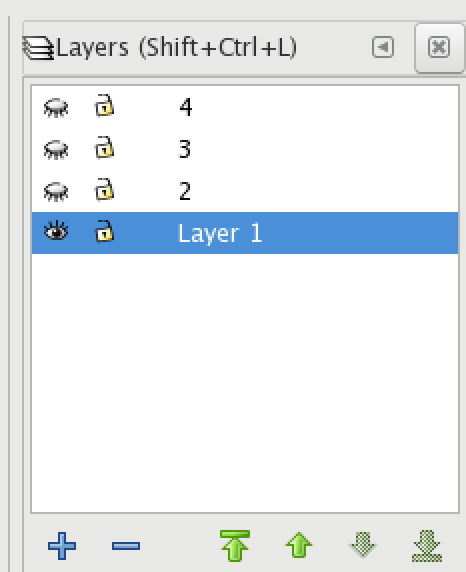
Bring up the Layers window, and duplicate the current layer until you have as many as there are rectangles - in my example, that would be three times, for a total of four. Number them sequentially. Hide all but the first layer, and double check you are actually working on that layer - it will be highlighted in the Layers window.
Save the design as an Inkscape SVG - this preserves the layer information.
Starting at the “end” of the design that would be fed into the machine first, select the second rectangle from the right (in my example), AND the design object that line bisects. I have selected them separately below just for clarification.
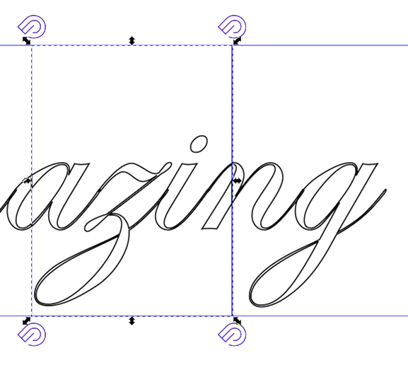
Choose menu option Path → Difference, and you will see that the left edge of the object (in this case, the letter ‘n’) will vanish.
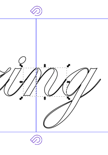
Now select and delete everything else to the left of that line, leaving only the first section that will be printed. Now we need to clean up the edges where the design element was cut - select the “Edit paths by nodes” tool, zoom in to the left edge of that element, and select one pair of connected nodes that are along the cut line, like this:
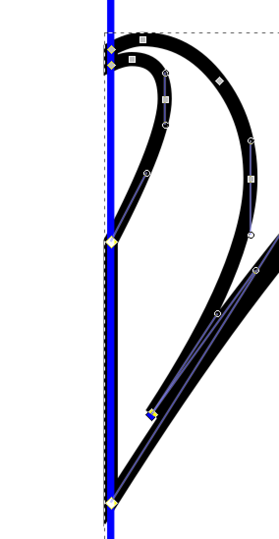
… and then use the “Delete segment” button in the toolbar to remove that line. Repeat for other cut portions of the design so that those elements are “open.”
Set the stroke path for the Snapmarks to something other than the rectangle and design elements. Save this layer as a Plain SVG file, using a descriptive filename. Now hide this layer, and unhide the next.
For the “middle” sections - in my example, the center two - repeat the steps above for both sides, and ensure you keep a pair of Snapmarks on both sides. I suggest you make the ones that will be higher on the bed the same color as the rectangle, as they will be ignored during the print (they are for alignment with the Scored Snapmarks created in the previous section). Repeat these steps until you get to the last section, and ensure the one pair of Snapmarks are the same color as the rectangle.
Now upload the first SVG file into the GF UI, and position as necessary. Set the design elements to process as required, the rectangle to Ignore, and the Snapmarks to Score. Print, then slide the material up until Snapmarks are near the upper edge of the bed. Return to the home screen, and upload the next SVG file. Set the ignore/Score/Cut parameters as before, making sure the upper Snapmarks will be ignored. Press the Snapmark icon, and after a minute, your design should be aligned.
Repeat for each section, relocating the material to keep the previous set of Snapmarks in the working area of the bed.
I hope this helps someone make good use of their passthrough slots!