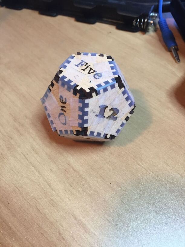
Hello. I’m new to a lot of this–Glowforge, Inkscape, lasers–and am making a 12-sided die with a parametric SVG pattern I drew. It came out well as a first test, but I’d like the sides to hold together with friction. I thought that the laser cutter was so precise, that that’s a normal assembly method?
The cuts are loose when assembled. I’m probably not accounting for something basic. How do I cut this for a tight fit?
I’m attaching a picture and the SVG file. Thanks for your thoughts.
Zack
What you are looking for is the search term ‘Kerf compensation’. I use a value of .007 on medium proofgrade for a fit that has to be tapped together with a tool. For something like a die that’s going to get bounced around, I would recommend CA (Super glue) to consolidate it.
Yeah, welcome to the wonderful world of kerf adjusting.
You didn’t say what program* you used to create the parametric model, but there are methods for kerf adjusting your designs in several of the major design programs written up in the Matrix.
*If it was Fusion 360, you can install the DXF for Laser plugin and it will adjust for kerf when you export the DXF file.
Kerf is the measurement of the amount of material removed by the laser. The laser “cuts” by vaporizing material - it’s not much, but it’s enough to prevent identical “fingers” from locking together.
You have to adjust your cuts to account for that, which is a manual process in a free app like Inkscape. Jules has an excellent tutorial on how to accomplish this for geometric shapes such as your tabs/fingers.
Yep, they’re right ^^^ I really didn’t have anything to add, just kinda wanted to pop in and say hi, welcome to the forum. It’s a pretty cool place and we’re happy to have ya. Go forth and laser all the things !
I like it. I can’t decide what will be more entertaining, trying to tap together a 12-sided die with a mallet or gluing your fingers together trying to get all twelve sides snug. As PrintToLaser said, if you’re going to roll it you may want to use glue; if it is for display than a friction fit will be good.
I’ve been confused over all the confusion about kerfs, because I’ve been thinking about them all backwards. I still had my brain in 3D printing mode, thinking of kerf as something you have to remove so your pieces will fit together. Since the laser does that for you by burning away a few molecules, everything fits without having to take a file to it, so I couldn’t see what the Big Deal was. (I still missed it, even when little bro @timjedwards explained it to me, and he’s a really good ‘splainer!)
NOW the light has dawned. In laser cutting, kerf is something you ADD to make the fit tighter! Brilliant!
Now I can graduate to just being confused about kerf, instead of confused about being confused about kerf. I feel like there should be a badge for this!
Exactly. In 3D printing, the manufacturing process adds a little material outside the defined shape, so you need to subtract a bit to correct for it. In laser cutting the laser is centered on the line of your design, burning away a little extra, so you need to expand your design to correct for it. A bit different from milling/routing, where you put the bit on the outside of the line, so there’s less to correct for. Not sure why lasers don’t operate the same way as milling. Perhaps because the laser is so much smaller than a router bit?
Coming from non-programmer and someone who doesn’t understand all the behind the scenes stuff about how lasers work and interpret different programs and file formats.
How hard would it be for the GF app to say, cut all lines of color of choice on the outside of the line and all colors of another choice on the inside and maybe another choice to cut down the middle like it currently does?
Seems simple enough in my mind and would make it easier to account for kerf but then again…maybe my mind is thinking about this to simply and still wouldn’t make a difference.
Non-technical answer: not that hard if you’re doing a square. It gets trickier where lines of different widths meet/intersect. Then there are probably cases of which side is the outside? Easy enough for a human to tell, harder for software. As I have to tell people at work all the time, “your use case is easy enough, but we have to program for ALL the use cases you’re not thinking of.”

 It’s a pretty cool place and we’re happy to have ya. Go forth and laser all the things !