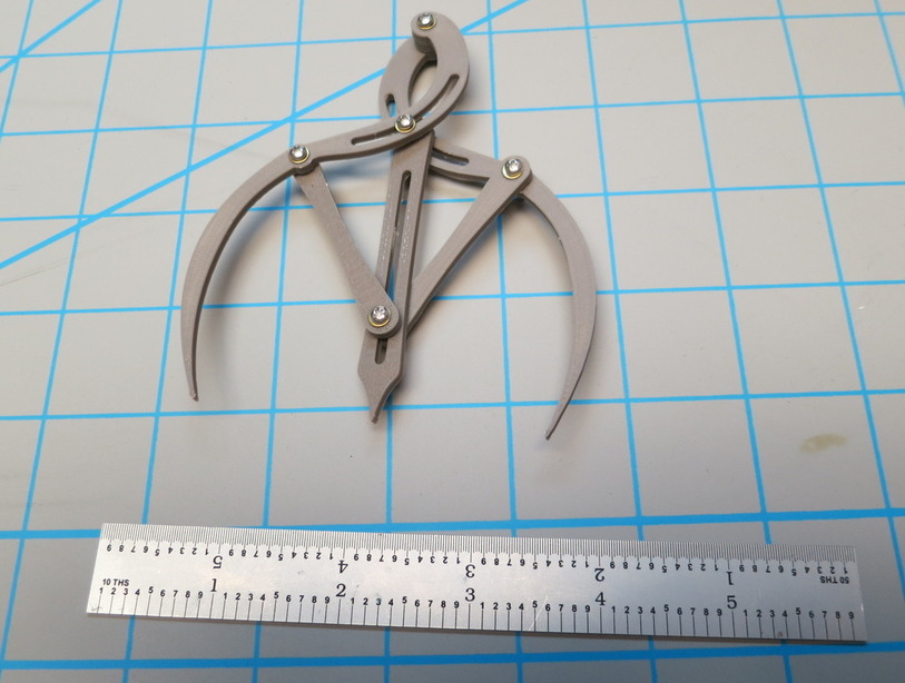
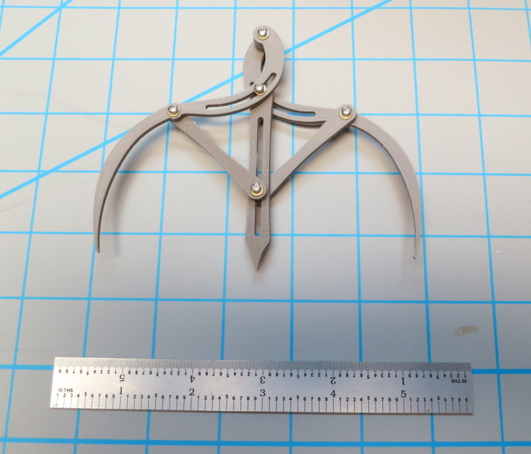
Your dividers printed pretty well, though I did add a little washer at the top to keep the arms on the right planes. This was printed on a Zortrax M200 with ABS at 90 µ resolution in Z and used 2-56 screws in place of the pins in your Onshape design. Nicely done!
13 Likes
Holy crap thats fantastic, thanks for printing it!
I meant to model some .1" washers, but time got away from me (I am really supposed to be working instead of reading forums).
Of course just looking at that print I can tell that the curves need adjustment to line up properly. My original intent had been to try an ellipse shaped slot to see if I could get the geometry to work.
3 Likes
That’s my guess, the geometry is not going to follow the parameters of the curve in the arm.
If necessary, The width of the arm could be widened to accommodate the required slot.
1 Like
I have made the drawings of the different parts. Nothing I can see or click on that allows me to export the drawing except as PDF or print it. There are several export options when you are in the assembly view or click on the parts in the left lower menu or a left click context menu. So I am able to export the DXF but on the Windows computer I have, there is a unicode converter that kicks in when I click on the .dxf. When I put the resultant svg into Inkscape, there is a very small drawing, with the line thickness way too big, but only parts and bits of the 2D drawing of the part I’m working with. I will work with some other vector program or 3D to figure it out.
No worries - the washer was a simple thing to add and the whole thing printed in a couple of hours, which is really short compared to most of my projects.
@marmak3261 - you must have defined an association between DXF files and that converter at some point. Once you get the DXF exported, find it in an Explorer window, right click it, and select “Open With…” from the pop up. That lets you pick a program that is different than the default to open it with. Alternately, you could start the program with which you want to read the DXF and then use it’s File function to open the DXF.
I drew something similar to these in SolidWorks. I got them to follow a path that was pretty close to a line with a round arc, but I think a spline might be required to make them work right.
2 Likes
I thought this looked cool so I worked on it for… longer than I probably should have… but I think I got it cracked!
Sorry for the long post! I’ve been working on this for a long time.
TL,DR - I thinks I got it, look at the pretty gif!
The difficult part is the curved slot in the two legs. I tried a circular arc first. That worked for the most part, but the tips didn’t always form a line.
Next I took a reverse-engineering approach. Instead of letting the groove dictate where the tips landed, I made it so the tips always fell in line and plotted-out where the slot would need to go. I opened it up so the tips were 10mm apart and placed a sketch point on that exact location of the leg. Then went to 20mm, placed another sketch point, and so on. I could then draw a spline with all the plotted points.
That worked pretty well. The tips landed where they were supposed to when they were opened to 10, 20, 30mm, etc. and were really close inbetween those measurements. Honestly, that probably would have been good enough. I decided to press on though.
I figured the shape of the slot must be a “normal” shape. Like @jkopel, I also thought the shape looked like it might be an ellipse. So I tried to fit an ellipse to the sketch points I plotted, but they would never fit quite right.
After that failed, I went back and plotted a few more points, this time I moved the leg pieces outside the range that they would ever be in while being used in real life. Like, I pushed them past the middle point to -10 and -20mm.
The additional points revealed that the extended path would actually cross over itself. I’m not a mathematician by any means but I realized that this shape was going to end up being more advanced than a simple circle or an ellipse. So I googled “mathematical curves” and looked through the image results for something that looked similar. I found the “prolate cycloid” and decided that looked pretty close.
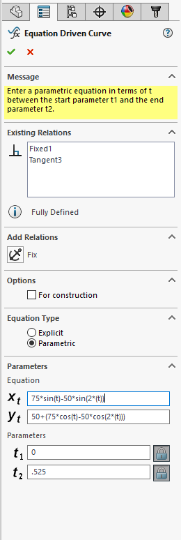
The next step was to try to recreate the prolate cycloid in SolidWorks. SolidWorks has a sketch tool called “Equation Driven Curve” that can be used to draw, uh, curves based on math equations. This was foreign territory for me so there was a lot of trial and error going on. I wish I could show or tell all the steps I took, but my approach was pretty unstructured so it probably recounting it would probable just confuse things more. Long story short: after tweaking the equations quite a hit it turned out a prolate cycloid wasn’t quite right either. ![]() It was reallly close, but not perfect.
It was reallly close, but not perfect.
I decided to plot more of the points. This time I noticed that the curve actually bends around and connects back on itself. So I went back to ol’ Google and spotted the “prolate epitrochoid” shape, rightfully referred to as the “Spirograph” curve/shape.
Here’s a cool website that lets you play with some numbers to visualize different epitrochoid (“Spirograph”) shapes…
http://www.mathplayground.com/Spiromath.html
In SolidWorks I played around with the Equation Driven Curve tool some more and found an equation that perfectly matched the plotted points (after many, many attempts). Eureka!
The two important equations are…
X = 75sin(t)-50sin(2(t))*
and
Y = 50+(75cos(t)-50cos(2(t)))*
I wish I could break these numbers down, but I’m afraid I wouldn’t get it right. Here’s the Wikipedia page that gave me the equations (which I simplified a little)…
And below is a screenshot of how the equations looked in SolidWorks. Note that SolidWorks uses “t” where the “Θ” symbol is used on Wikipedia.
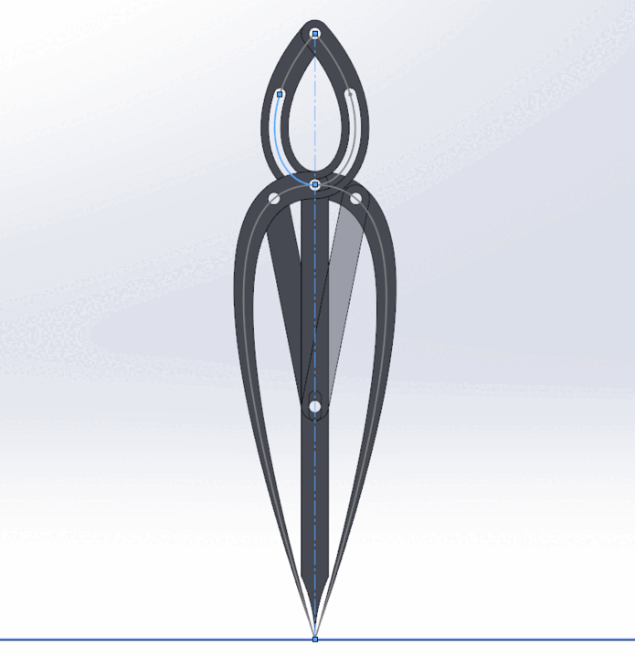
Basically, plotting all the points and finding the epitrochoid shape was key. The rest was just making a model that looks like an actual gauging instrument that could be cut with a Glowforge. Here’s a screenshot that shows the non-asthetic elements of the legs. There’s really not much to it!
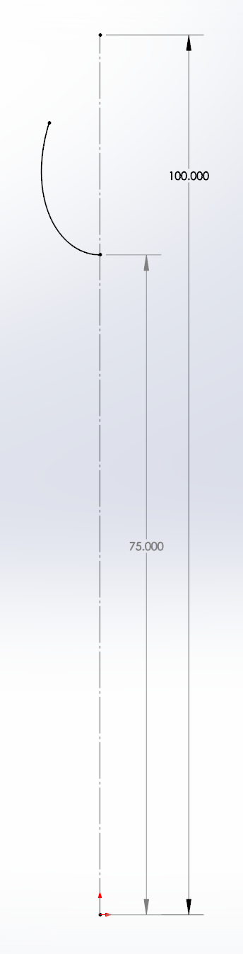
The dashed vertical line denotes the tip of the leg (on the bottom) and the axis of the pivot pin (at the top). The solid curve is the product of the Equation Driven Curve tool. I included the 75 dimension to show that the equation driven curve starts at (0, 75).
I’d share the file I made, but I don’t have an Onshape account. Also, SolidWorks is a complete and utter piece of worthless garbage when it comes to exporting files. The forum won’t let me upload a zip file, I can understand why not though. What else… Illustrator wouldn’t open the DXF and DWG I exported, though it looked like the lines became faceted anyway (thanks SolidWorks!) so they wouldn’t have been any good anyway. I haven’t installed Rhino yet (it’s awesome about opening and exporting different filetypes!) so I can’t use that. Um… I also haven’t installed Fusion360 yet, but I prolly should. I’ll deal with the sharing of the file later.
28 Likes
Nice work! Elegant…
1 Like
Beautiful! I <3 your brain!
1 Like
That’s pretty awesome! Great work!
Yea, I had issues exporting SolidWorks files as well. I had to export it to DXF and then fix it in AutoCad. @dan, is it possible to add Solidworks files (.sldprt, .sldasm) to the approved upload list?
3 Likes
You win at dividing (and multiplying, and modeling, and googling  )!
)!
Those are fantastic, and I am super impressed at your sticktoitivness to find the right curve. I bet the original dividers that @madebynick used to start from were no where near as accurate!
If you do want to share these just register for a free OnShape account. OnShape can import Solidworks “pack and go” zip files. Then you can make the file public and we can all play with its three legged goodness!
5 Likes
Your tenacity is impressive! Thank you for the lesson, very nice!
2 Likes
Very cool! Great tenaciousness! Reminds me of the book “How Round Is Your Circle?”
2 Likes
Thank you so much for this work, especially the documentation. I vote this the #1 all time favorite post in the forum. You demonstrate all the goodness that is possible. They’ll have to invent another badge for this.
3 Likes
Wow @Hirudin thats awesome! 
1 Like
@Hirudin - if you’d like to email me the SW files as “Pack and Go”, or even individual parts files, I’ll get them into Onshape and make them public with credit to you.
2 Likes
Seriously impressive work! I was following along with @madebynick’s project, but never expected anyone to sort out how to actually make it align like that. Very cool!
4 Likes
This is great stuff. Thank you for sharing your methods and findings!
I’ve signed up for an OnShape account after @jkopel recommended it as a potential tool to solve the problem, but have not yet learned enough of the software to be able to model in such detail.
As an alternative non-software solution, I started drawing up a version which would hold a pencil and draw the correct curve - pentagraph style - but haven’t tested it yet. I’ll be interested to know how similar our results are.
Thanks again for sharing!
5 Likes
Thanks everybody!  I tend to be a bit verbose at times so I was nervous that most people would see that novel of a post and just skip over it. That gif must have been a good opener.
I’ll get an OnShape account tonight and upload the pack-an-go zip file. Then post the link here.
Thanks again for the complements!
3 Likes
@Hirudin slap a bitmap on here with the pieces and I’ll vectorize it. Easy peasy.
1 Like