What a cool experiment! There’s a tremendous amount of useful information in this thread. I agree, the best bet is to use a laser power meter to measure what’s actually going on. Your Glowforge will dynamically vary power (as someone mentioned) so the meter will give you “ground truth” numbers. We use something similar for informal spot checks at the office (lots of tiny circles on top of the sensor of a laser meter).
8 Likes
Seems to me that you could mount the sensor to the gantry and then do long vertical lines instead of circles? This would allow you to meter power at a certain x position, help identify alignment problems.
I suggest it because I wonder how much power would be affected by clean corners if you’re using tight circles. Granted clean corners is about acceleration effects when turning sharp corners, I just wonder how tight the radius could be before the power would be modulated to compensate. Perhaps this is a non issue if you’re using slow speed settings, the slower you go the less acceleration effects come into play.
Science, man. We need a control group! 
3 Likes
Any chance that you or someone who’s doing the spot checks could share the protocol for getting those numbers from the laser power meter???
Reading into how these things tend to work…
Laser Power Sensors Introduction.
I think this might be a decent explanation. It makes sense to me.
One might not need to do as tight of a circle as the file I put above. So long as you are hitting the pad, it should read out accurately (accurately being within the tolerance of the meter being used)
Since all the heat absorbed flows through the thermocouples (as long as the laser beam is inside the inner circle of hot junctions), the response of the detector is almost independent of beam size and position. If the beam is close to the edge of the inner circle, some thermocouples become hotter than others but since the sum of all of them is measured, the reading remains the same. Generally, Ophir specifies ±2% uniformity of reading over the surface or better.
Looks like they even raised you one perhaps! But, these are pretty expensive meters. Over $1,000.
Ophir now has the new BeamTrack thermal sensor that can measure beam position and beam size as well as power. This innovative device provides an additional wealth of information on your laser beam – centering, beam position and wander, beam size as well as power and single shot energy. The BeamTrack sensor is illustrated schematically here and works as follows: the signal coming from the sensor is now divided into 4 quadrants so by measuring and comparing the output from the 4 sections we can determine the position of the center of the beam to a high degree of accuracy. In addition to the 4 quadrants, there is now a special proprietary beam size detector. After processing outputs from these various detectors, the user is presented with the beam position as well as beam size. Note that the beam size is calibrated only for a Gaussian beam of >3mm but for other beams it will give relative size information and will indicate if the beam is changing size.
This looks interesting: https://www.ophiropt.com/laser--measurement/laser-power-energy-meters/products/BeamTrack-Power-Position-Size-Sensors/BeamTrack-Power-Position-Size-Thermal-Sensors/50(150)A-BB-26-QUAD
The BeamTrack series 50(150)A-BB-26-QUAD laser measurement sensor measures laser beam position as well as power and energy. It has a 26mm aperture and can measure position to 0.1mm accuracy. It measures power from 40mW to 50W continuously and to 150W intermittently.It can measure energy from 20mJ to 100J.
1 Like
I’ve finally received a Mahoney Laser Power Probe. According to the instructions that came along with the probe, the black absorbing block is to be exposed to an unfocused laser beam for 29 seconds. After a wait of an additional 25 seconds, laser power is read from the analog dial. Seems simple enough. Given the comments already shared on this thread, here is my plan for measuring laser power from the Glowforge:
- Remove the crumb tray
- Place the Mahoney probe on the bottom of the Glowforge with the dial near the front edge
- Block air assist fan
- Expose the black absorbing block for 29 seconds using a 20mm x 20mm spiral vector image
- Wait and read the dial
To expose the block for the requisite time, I’ve created a simple spiral path that takes 29 seconds to cut. I’m hoping that the continuous spiral will mean that the Glowforge is at constant power the entire 29 seconds.
I’m open to any constructive suggestions/comments on this approach and/or improving it so the readings are as accurate as possible.
2 Likes
Sounds like it’s worth a try! What’s the worst that could happen?

4 Likes
Well…I’m up to 60% full power and my Glowforge hasn’t even gotten hot. So…I think the Earth is safe. 
2 Likes
Very curious to see your results!
Yeah, well, I think I screwed this up! Somehow, on one of the runs at high power, I didn’t have the meter’s absorbing surface enough out of focus and the laser etched the spiral onto its surface. Not sure if that will affect the meter’s readings or not??? I’ve contacted the manufacturer.
2 Likes
The manufacturer of the power meter said I just need to expose the non-etched area of the absorbing plate. Made some measurements that seem to make sense, but are lower than expected (see graph below). Here’s a photo of the set-up:
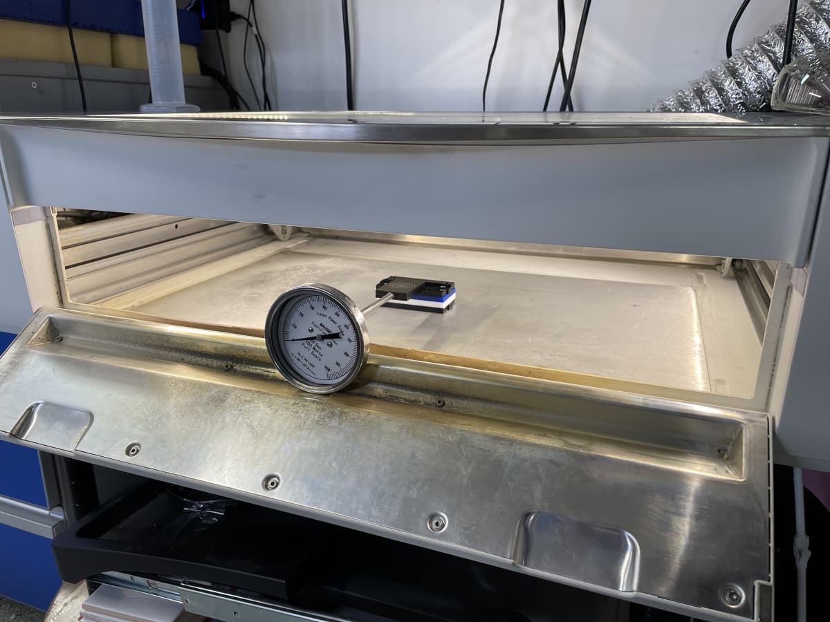
I fooled the Glowforge with magnets to allow for running with the front door open. I reduced the size of the spiral image and located it on the un-etched area of the meter. I also placed a 1"-thick piece of foam on top of the black absorbing surface to fool the Glowforge during the auto-focusing part of the print. The foam was removed before the start button was pushed for each run. After exposure and waiting about 30 seconds I took readings from the dial when it reached its highest value. Like many analog gauges, I had to tap it to get the needle to move freely. Here are some preliminary results:
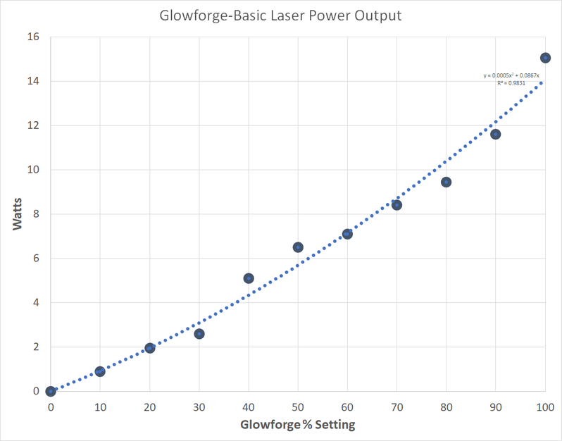
For a 40-watt laser I didn’t expect readings of <16 watts at Full Power. This is at the end, so maybe there’s that much power loss through all the mirrors???
Shouldn’t be. I took the reading before the head mirror on my other lasers and generally saw from 80-95% of the laser’s advertised power. Wasn’t surprised by the 80% readings as those were from a cheap chinese laser which are notorious for overstating their tube’s power.
The power loss in the process is from the power supply to the laser. From the laser to the material should be negligible drop-off with good lenses (and the GF lenses seem to be pretty good). I think there’s something we’re not considering in the design of the testing protocol.
1 Like
Just a thought here… I think rather than trying to fool the autofocus system and this other stuff, I would just remove the lens. I’m pretty sure @evansd2 has messed around with some scores like this in “extreme defocused tests”. The beam width is small enough still that it won’t hit anything inside of the head after the mirror.
As far as the power, not sure. Your r-squared value is probably within the + / - of the tool itself. It’s almost like the reading is off by a power.
The optics won’t eat much power at all, so long as they are in good condition. Each of those should be in the 99%> transmissibility range, so you have a small amount of cumulative loss, but not much.
I’m assuming you probably followed the procedure correctly, but I did see an Instructable on using it.
It mentions 15 seconds exposure, calibrating the face plate to zero, and also cooling it off between runs (either by just waiting for it to fall to 0 or cooling it more rapidly in water).
Yes…I’m following the steps outlined in that Instructable. I’m very careful to get the meter to zero (ambient temperature) before each reading. The manufacturer’s instructions indicate the black absorbing surface can be cooled in RT water so I’ve been doing that to reduce the time in between readings. However, the time between readings has still been between 10 and 30 minutes just so I’m sure the needle really is starting at 0.
I just tried printing the spiral image at 50% after removing the lens and locating the absorbing black surface about 15mm below the printing head. After exposure, I got a reading of 6.8 which is very close to what I was reading with the lens in place.
Earlier in this thread, there was mention of the Glowforge modulating it’s output on corners and turns, etc. I wonder whether this spiral image is maybe not the best choice???
1 Like
What speed are you running the job at?
- The entire exposure has to take 29 seconds for the meter. I made the spiral and the lines the length so it takes 29 seconds.
1 Like
That’s my thought.
I’m thinking a raster engrave at stupid high LPI (1350) of a very small square with multiple passes to eat up time is probably a better approach as long as it’s firing in both directions of the raster (otherwise you’ll get half the heat sinking as it fires left to right but not right to left on the line’s return).
You can enter a number in the passes field and are not limited to the drop-down values.
I’d be really surprised if it’s modulating the power on something like that at that speed. The Glowforge handles curves relatively well.
Dan mentioned above that they use lots of tiny circles. Perhaps they know how the power is modulating for a given design though and can extrapolate out the output from that.
1 Like
I very much appreciate the suggested ideas! I tried a raster engrave of a small square with speed/density settings that would make the print last 29 seconds. When I ran it, I noticed the laser cycled on/off as the head went back and forth. I’m printing with the lens removed so the LPI value probably isn’t very relevant. When I ran it at 50% power for 29 seconds, the watts reading was less than half of what it was with the spiral. I’m thinking the on/off cycling during a raster engrave means this isn’t the way to go. I’ll give the “tiny circles” approach a try.
A 2mm circle with 7 passes at speed=100 took 29 seconds and ended up with a reading of 6.2 watts. That’s consistent with the readings I obtained using the spiral to construct the curve earlier.
This is probably kind of a pointless post from me, but figured that may be better than saying nothing. I’m fresh out of ideas. I guess it would be nice if you had access to another laser to compare results or that it’s working correctly.
1 Like