I was thinking along the same lines and, actually, have access to another laser engraver to see what kinds of values I get from it. It’s a cheap Neje laser engraver that’s advertised as having a 30W power module, optical power output 7.5W. I don’t understand how a 30W module ends up with 7.5W of optical output, but it will be interesting to see if the laser power meter registers 7.5W after a 29-second exposure at full power. I’m going to test it right now. Stay tuned!
Using the spiral vector image at 10mm x 10mm, running at 220mm/min at constant (M3) full power, the 29-second exposure resulted in a reading of 5W on the laser power meter. I’m controlling the Neje laser with LaserGRBL That’s not the 7.5W the manufacturer promised, but it’s closer than what I was getting on the 40W Glowforge (~15W at Full Power). I’m assuming the meter is correct and calibrated and is able to totally absorb the light coming from these lasers even though their wavelengths are different. I’ve run out of ideas and will need guidance from Glowforge engineers or someone very knowledgeable in the inner workings of the machine.
1 Like
Pretty much the same way 400 watts in results in 40-watts out on a co2. ![]() I’m not sure why, but a lot of the diodes seem to advertise using the power consumption rather than output.
I’m not sure why, but a lot of the diodes seem to advertise using the power consumption rather than output.
I think diode lasers are somewhere around 55-65% efficient at best, compared to like 10-20% for a co2.
Interesting results though… it’s not scientific, but I know the Glowforge performs (cutting rates) as well as or better than other 40-watt systems. So the results are definitely intriguing.
It’ll keep the head from moving much on the Y axis the higher the LPI as it is overlapping lines at 1350.
Then multiply the meter result by 2 since it’s cycling off on the return trip for each line so it’s only 50% power on effectively. Or run it for 58 seconds to get the equivalent of 29 seconds of constant power.
I engraved a 10mm x 10mm square at 50% power at a speed setting (220) that resulted in a total print time of 58 seconds. If the laser is off half the time as it rasters back and forth, that should result in a 29-second laser exposure. The result was a reading of 8.1 watts. After watching this run, I think the laser is on more than it’s off, but it would be hard to determine the exact timing. If it was on more than off, then I exposed the absorbing block for more than 29 seconds, thus the higher than previous reading for 50% power. In any event, none of the approaches I’ve tried are getting me to readings that make sense. On a 40W laser running at 50% power, I should be approaching, if not reaching, values of 20 watts or so. Something else is preventing me from getting correct values.
FWIW, and this is for book knowledge more than anything else, the numbers described aren’t describing percentages. For example, Full Power is supposed to be ~5 watts difference between the Pro and the Basic (45w v 40w), but the precision power values (1-100) are supposed to be the same between all of the systems. On the Pro, that leads to at least a 5-watt output drop off between 100 and Full.
Your testing was supposed to be the testing that gave us percentages! 
I’m not sure I follow what you’re saying, but you’re right…my intention was for the laser power meter to convert the % values in the Glowforge app into actual power values (e.g., watts). I’ve done that, but I don’t believe the values I’m receiving from the power meter. Not sure why the values are so low, for example. It’s also frustrating that the “Speed” settings on the Glowforge are unitless and non-linear. When I’ve tried to set a time for laser exposure of the absorbing block on the power meter, I have to guess at speed settings to find the right one. Maybe someone, sometime has constructed a calibration curve to relate the GF speed settings to actual speeds in mm/min???
I’m just saying that the power levels, despite being 1-100 and then full are not percentages. So 50 power is just 50 Glowforge power not 50% power.
Here’s a spreadsheet for speeds using Inches Per Minute. You’ll need to make a copy to make edits to it:
I get it. The numbers are labeled “Precision Power” and I inadvertently stuck a % to them since they ranged from 1 to 100. However, there does seem to be a linear relationship between “Precision Power” and watts from the graph I created. I fitted a polynomial curve to the data, but a linear relationship actually fits the data better. I know that doesn’t answer the question of why the power values are so low from the meter. Thanks for the speed unit conversion spreadsheet!
Are you the author of the “Glowforge Unit Conversion” spreadsheet? If so, can you clarify what the “Old Units” and “New Units” are? I’m thinking the “Old Units” are the speed values in the GF app and the “New Units” are in Inches/min???
I’m not. Glowforge actually released that. The pre-release units used in/m as their original speed settings and that was changed to the “new units.”
So, the old units is in/m and it converts that to the current 1-500 or 1-4000 (for engraves) that the machine uses now.
1 Like
Does that part translate as the machines at the time only went to 1000 zooms? Is there a linear relationship to assume from 1-4000 zooms?
I’m digressing from the main issue of laser power measurement, but I’m not relating to the unit conversion spreadsheet provided by Glowforge. I prefer a chart so I created this:
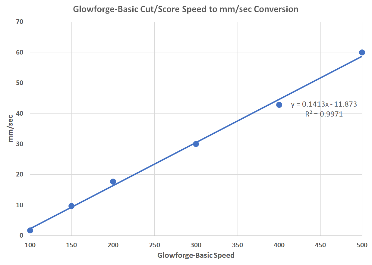
There’s a highly linear relationship between the cut/score “Speed” setting and mm/sec. Note that “Speed” values of 300 and 500 are exactly 30 and 60 mm/sec, respectively. Not sure that was the intent when the Glowforge was created, but I believe it helps validate the other values used to create the chart. The regression equation can be used to create an exact conversion in a spreadsheet in anyone’s interested.
1 Like
How did you arrive at 300 speed is exactly 30mm/s?
From the spreadsheet calculations, 80.5 inches per minute is 300 cut speed: 80.5 inches per minute is 1.34 inches per second, which is just over 34mm/s.
For speed 500, that’s 2.61 inches per second, which is 66.294 mm/s.
I’d do it at Full power & your 220 speed setting. You’ll get 58 seconds under the head but roughly half that with the laser on - it will be on when engraving the line left to right and then off as it returns to its starting point to engrave the next line. (I think it’s doing that vs bi-directional engraving where it would be lasing virtually all the time.)
As @jbmanning5 noted, the power & speed scales are non-linear (frustrating) so 50 could be only 20%
(or 70%) power - just no way to tell right now.
I think what I would be doing here is concentrating on full power readings since we know the neighborhood of expected results for that. That the readings are pretty consistent, but way lower than expected, is a little odd.
I guess if I wanted to rule out anything more, I’d figure out a way to fasten the meter between the head and the left side of the gantry. Doing that would also eliminate any focus stuff or setting up a job of an exact length/time - just go nice and slow on any cut and kill the job at 29 seconds.
Yeah that’s a good idea. See if it can be finagled in front of the left mirror. Maybe design a little fixture to rest the dial portion on the coolant reservoir that places the absorber in the beam path but out of the way of the moving parts.
I created a 300mm line to be cut and tried different speeds (e.g., 100, 150, 200, 300, 400, 500) and started to print. Once the GF app showed how long the print would take (in seconds) I recorded the values. For the speeds above, I got the following times: 177, 31, 17, 10, 7, 5, respectively. Each time, then, is how long it will take the GF at each of the speeds to cut a line that’s 300mm long. I divided 300mm by each of the times to get mm/sec for each speed. That resulted in the following values for each speed (1.69, 9.68, 17.65, 30.00, 42.86, 60.00). Therefore, Speed=300 corresponds to 30.00 mm/sec and Speed=500 corresponds to 60.00 mm/sec.
I 3D-printed a holder for the laser power meter that slips over the head of the GF printer. I don’t slip this holder or power meter onto the printer head until the initial homing and centering process is complete. During those steps, the head moves too close to the bottom edge to allow for clearance of the meter that sticks out several inches. Anything printed with the power meter attached has to be located near the top of the GF bed.
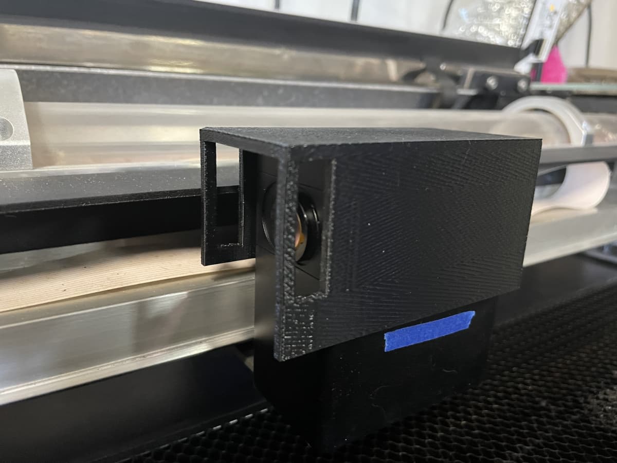
The power meter slips into a couple openings on the front (left left) side of the printer head and completely covers/intercepts the light path.
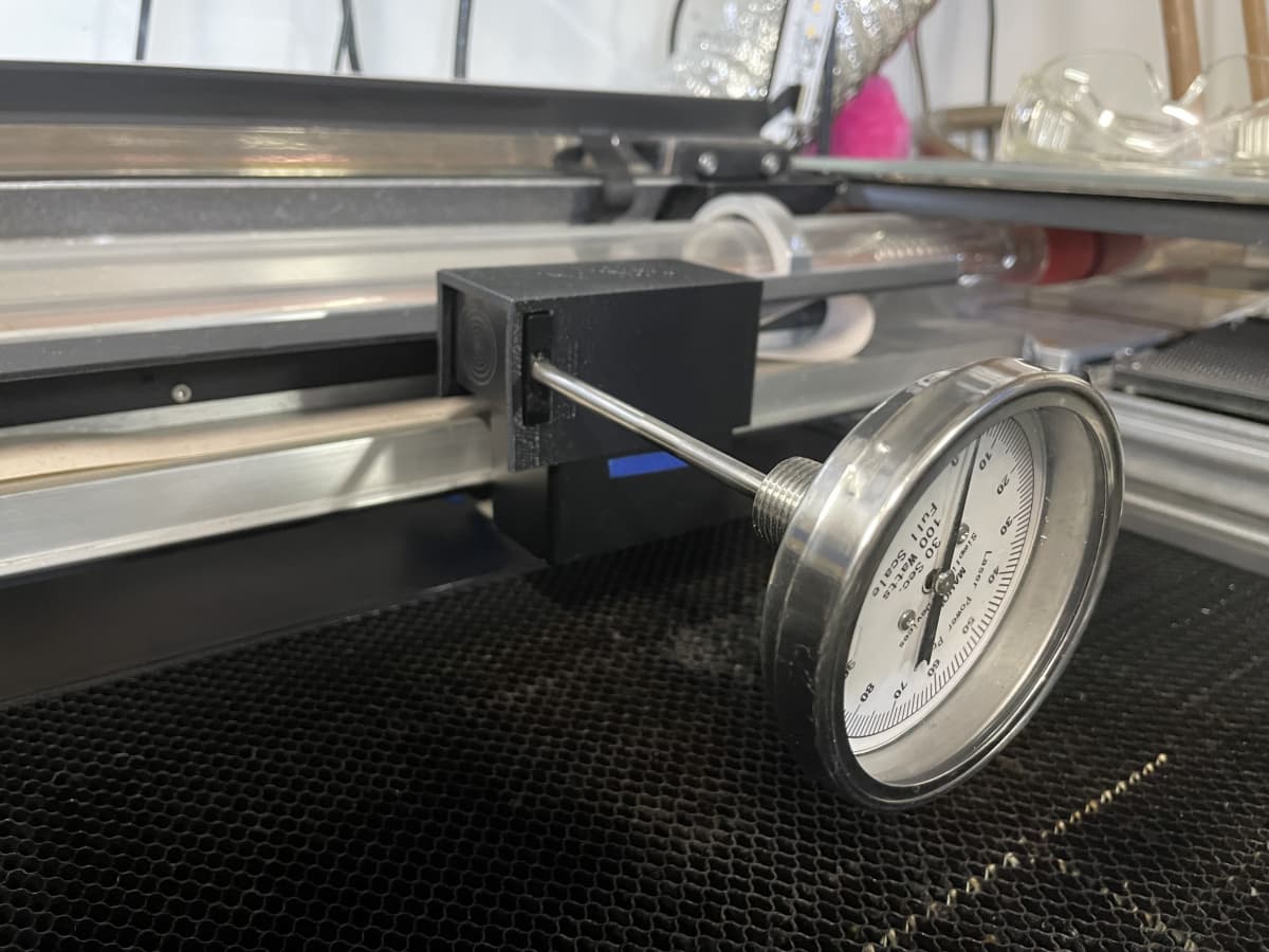
How does it work???
I printed the spiral vector image that takes 29 seconds using Full Power. After waiting the requisite time after exposure, the meter read 23.2 Watts. A video recording of the run can be found here:

While I’m still not getting the 40 Watts I expected, using this approach did increase the reading from ~16 Watts that I got from readings through the print head with the lens removed.
I’m still wondering why I’m only getting about 60% (~23W) of the 40W rating of the GF. Maybe that’s the best it can do??? Maybe the power meter is not recording accurately because of the etching I made in early runs??? BTW…the manufacturer is sending me another meter at half-price so I’ll have another meter to test in coming days. Maybe there’s still something I don’t understand about how to make these measurements???
5 Likes
Clever. Nice clean design.
1 Like