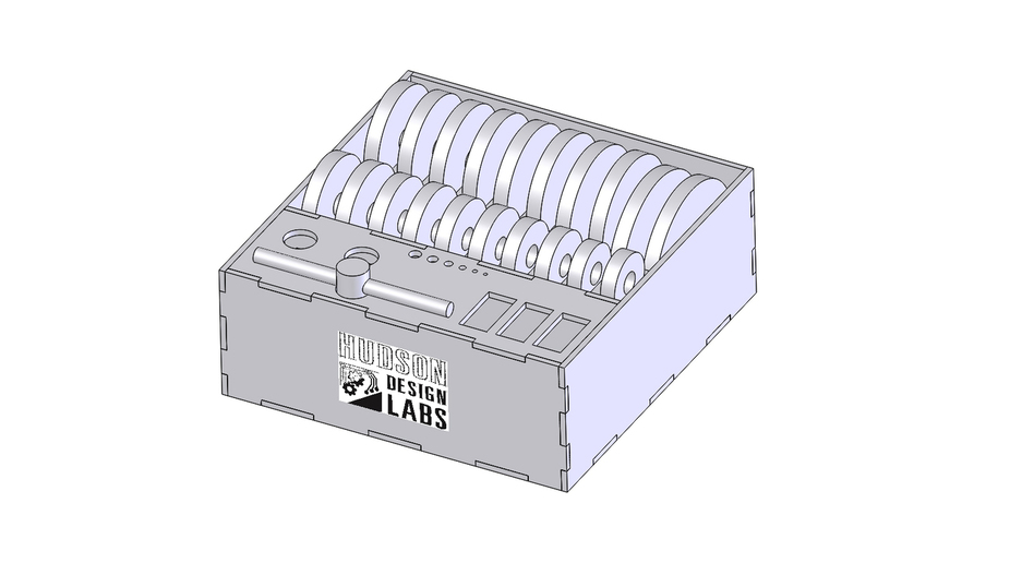
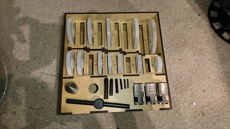
After several years of feeling restricted and frustrated trying to do all my lathe work on a cheap pen lathe I broke down and bought a 7x14 mini-lathe for metal work. It came with sets of gears to adjust the feed for threading, a bunch of hex wrenches, and a set of inside and a set of outside grab jaws for the chuck. And of course the chuck wrench. I knew that it wouldn’t be long before they were a mess. Since I wanted to get used to designing for the laser, I made a storage box for everything. The gears are designed so they are all even with the same top plane to make them easier to pull out.
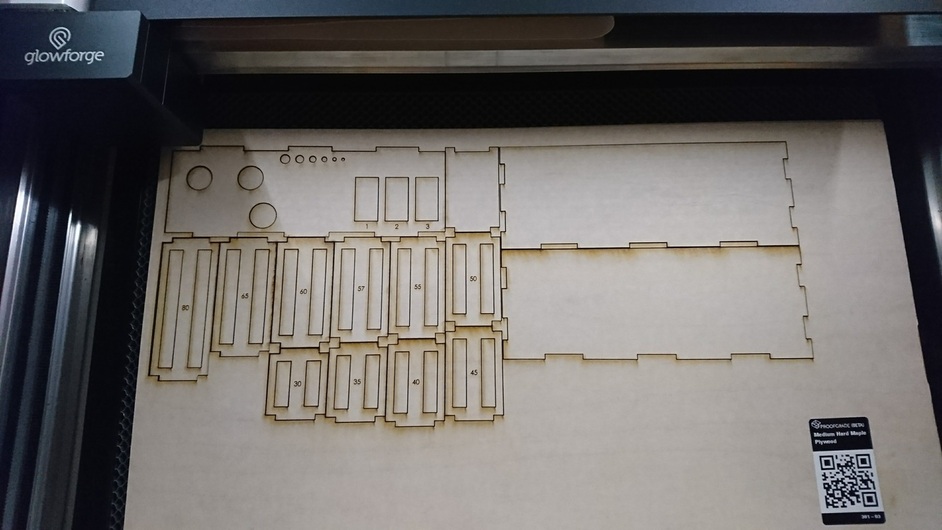
The design was done in SolidWorks. I used a 0.3 mm kerf (0.012 in) split 1/3-2/3 since the laser path seems to be slightly off center of the line. I desgined all the parts and checked fit and then imported the plan view of each part into a drawing, added the text on a separate layer, and exported to PDF. The logo was added in the GFUI using Add Artwork.
The parts were cut from Proofgrade medium maple plywood.
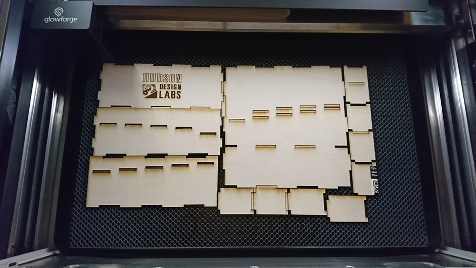
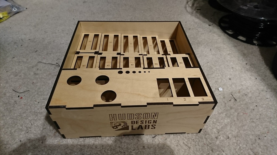
After weeding, everything looked good. The nice part was that all the joints snapped together with only a little encouragement with the deadblow hammer.
The numbers next to each gear set are the number of teeth on the gear for easy reference and the chuck jaws are numbered also. The holes for the hex wrenches are a tight enough fit that they can’t be confused and there is room for two deadcenters. I don’t know if my live center will fit. That and the tailstock chuck may need another stand.
Total time start to finish was about 8 hours in the design and about 35 minutes laser time.
Thanks! It is more that I know if I don’t start organized it will decent into chaos. If something has a place for everything before I even start, like things that come with organized storage cases, I generally keep them in the case and it stays organized. If not, who knows if I will be able to find what I need when I need it.
I can’t recall anyone every discussing this. I’ve just counted on the kerf splitting the middle. I’m curious about your experience and might have to do all my kerf tests with the production unit.
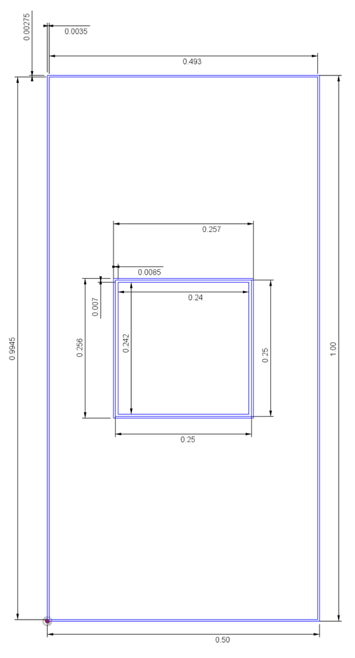
I did a small test piece on 3.3 mm maple hardwood. The piece was 1 inch by 1/2 inch and had a 1/4 inch square cutout. The result measured 0.493 by 0.9945 and the 1/4 square cutout measured 0.240 by 0.242 with the hole measuring 0.257 by 0.256. I thought it was odd too, especially since the 3.250 circle I cut out of the same piece of wood two weeks ago was exactly 3.250.
The 1/3 out 2/3 in seemed to work well though for everything but the holes which ended up slightly small.
This confusion, and the perpetual confusion about kerf that has been so pernicious on this forum for the past two years, is a big reason it would be a lot better if Glowforge actually implemented kerf compensation in the GFUI.
I calculated the kerf by taking the difference between the resulting dimension of the hole from the 1/4x1/4 cutout and the cutout itself. Subtracting .242 from .257 gives 0.015 inches. Based on several different measurements, I came up with an average kerf of about 0.012 inches, or about 0.30 mm. Since I did the design in mm, I used 0.30 mm, split with 1 mm out and 2 mm in based on the center cut of the 1/4 inch hole.
The 0.012 inch/0.30 mm kerf has been substantiated with other results from other testing on this forum. Note that this is for holes and joints, so it takes into account both sides of the joint as a design adjustment. The single cut kerf should be about half what I used. Perhaps I should have said double kerf. I am still getting used to applying terms correctly for laser stuff.
Are you saying that you offset outside lines by 0.1mm and inside lines by 0.2mm?
Because that’s not what you should have done. Even if you were convinced that the kerf varied somehow (which is unlikely, especially at laser-cutting speeds), you should have done 0.05mm out and 0.1mm in.
Not quite, sorry for the decimal error. The double-kerf offset was to reduce the total width of a slot by 0.10 mm and increase the total width of its corresponding tab by 0.20 mm. Again, I am dimensioning total width, not offsetting individual lines. This would make an individual kerf offset of 0.05 mm and 0.10 per your numbers.
Unlikely or not, I have measured variance of the kerf. It seems to be a difference between X and Y speed, though I haven’t done any designed testing.
A difference in vertical cuts compared to horizontal is believable. If the laser spot is somewhat oval-shaped the kerf would indeed vary. To compound that problem, the oval might not be oriented with either axis, or it might only have an anomaly in one area, which would then only show up at certain angles.
I agree that a variance in the speed of the X and Y motion would have an effect as well. That’s one of those things that I would hope would have been anticipated and avoided though.
Yes the speed along the cut should be the speed selected in the GFUI except where it has to slow down for corners. A different X and Y speed would be a nightmare unless power was changed to compensate.