Glowforge Owners Forum
Lid Camera Alignment Examples FTW
Everything Else
eflyguy
June 27, 2018, 12:55pm
9
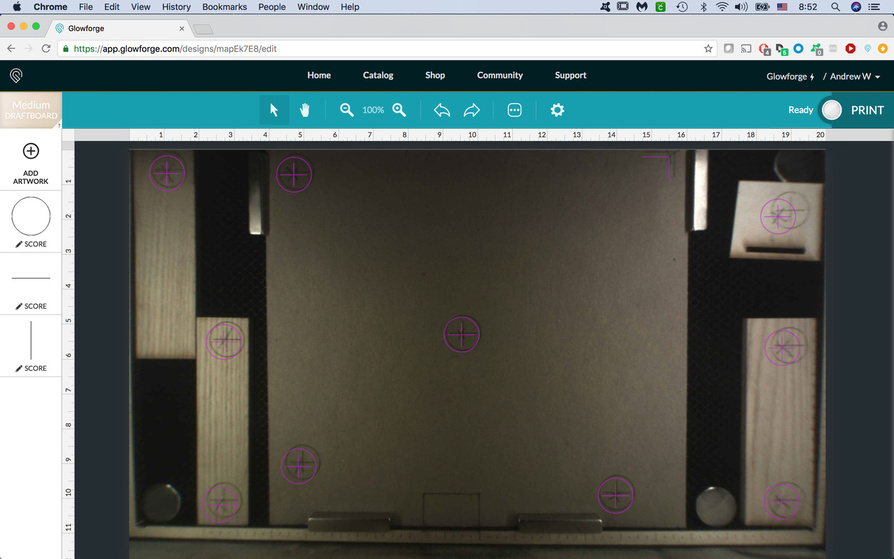
image
1264×790 148 KB
5 Likes
show post in topic