Other than stuck calibration, the most consistent concern in topics seems to be wondering about alignment with the lid camera and GFUI. Folks aren’t quite sure what to expect. Perhaps different machines behave differently. I am lucky to have a Glowforge that doesn’t get stuck in calibration loops and I am very happy with GFUI and lid camera alignment. I know there are times when some numeric positioning would be great and there is room for improvement here. But I’m just posting an example of what I get using non Proofgrade materials and manually positioning things all around the bed to use up scraps.
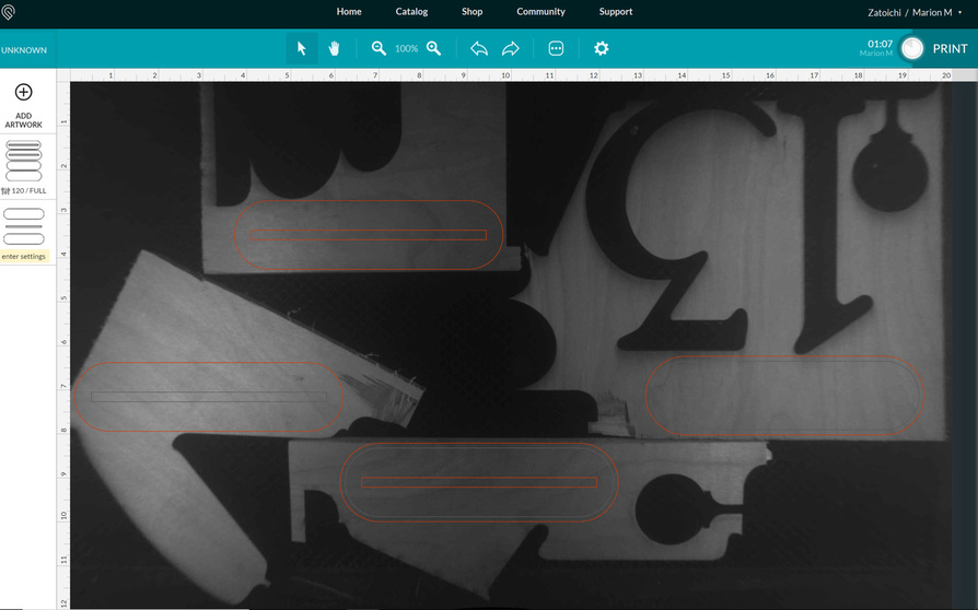
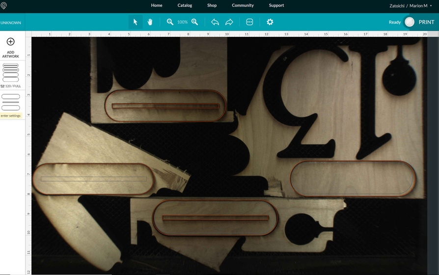
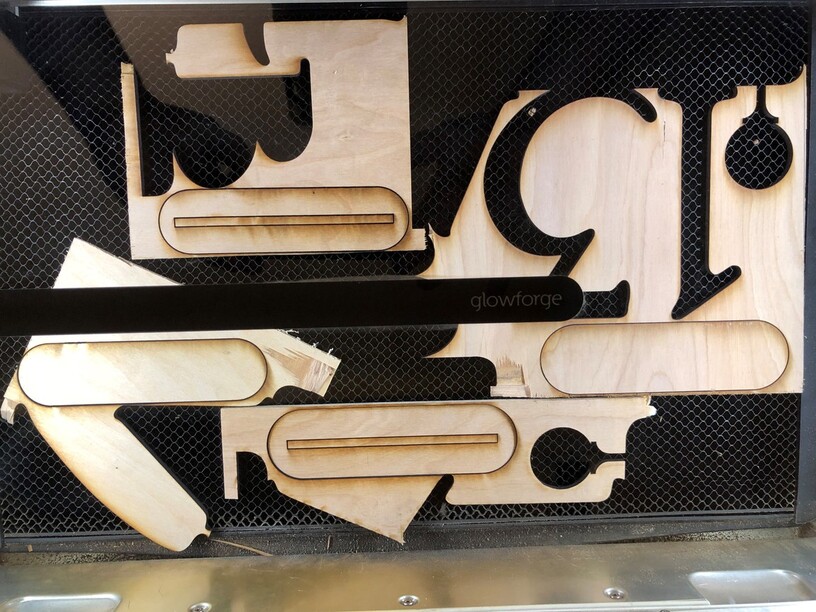
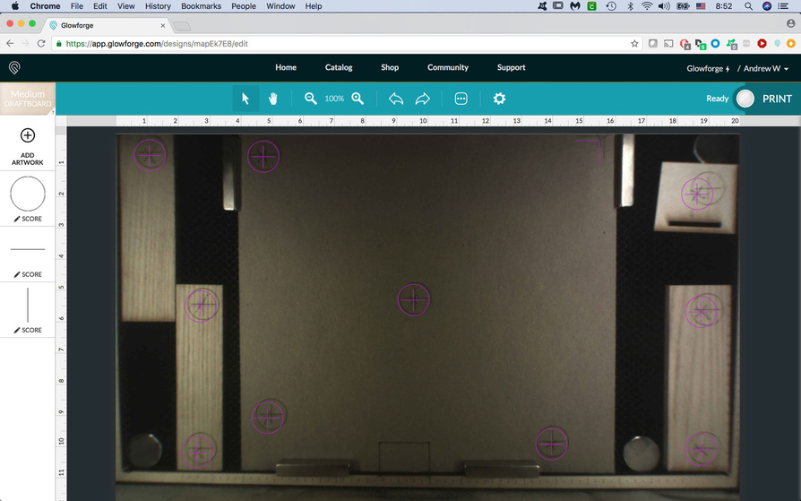
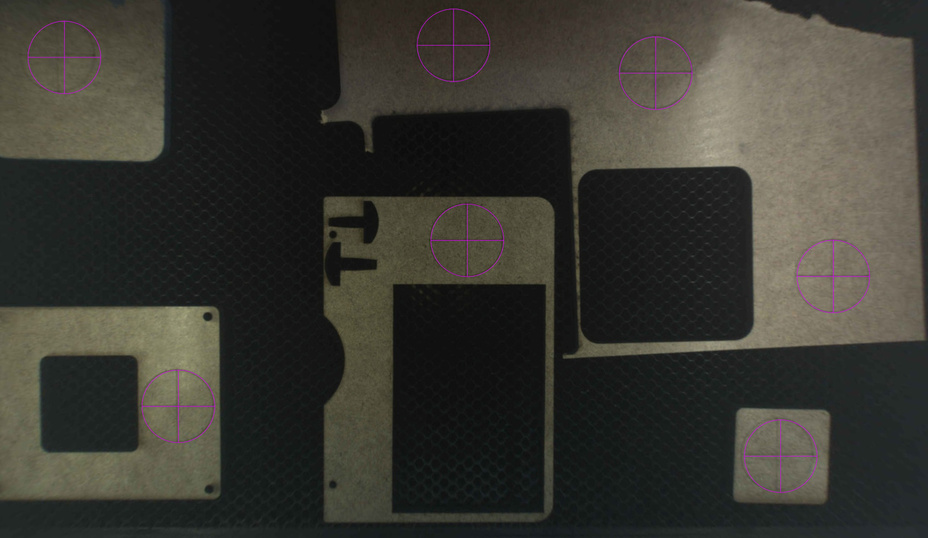
Here is a bed shot of the GFUI positinging the four objects on four different pieces of material. Each had to go in the spot they needed to with only a half mil to spare in some cases.
Now the real test would be to take the four pieces of wood that I cut out. Lay them at various places in the bed and engrave something on top of them. Will try that.
In the meanwhile, this is a pretty good example of the Glowforge cutting where the preview says its going to cut.
Back in the day, there used to be a considerable number of queries about the lid not being flat, ie there seemed to be a slight rise in the middle. Now, whenever problems of placement come up, most replies seem to concentrate on the ‘flatness’ of the material in the bed, and I wonder if there really is an occasional problem with lid location or flatness.
Given that individuals may have a consistent error, but that it varies on where they place there work on the bed, I’m not sure how the lid camera interacts with the gantry camera, and how this might effect the mapping of the surface of the bed.
John
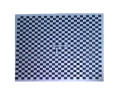
I wish they would give us an 11 x 17 PDF alignment tool, we can print out, to do the alignment procedure ourselves. I use industrial vision systems all the time and all of them have a way to compensate for lens distortion. Right now I feel like this is the biggest problem I’ve seen with this laser.
Yours is way better than mine. My current machine is off significantly more (pretty close to that 1/4" spec) than my PRU was. Oh well. I just adjust via “Kentucky windage” and everything comes out fine.
That’s just crazy to have that kind of variation among the machines. Thanks for demonstrating this. That really helps me put the problem in perspective.
My placement discrepancy is towards the closest edge of the material, and the closer to the edge, the worse it gets. In other words. if you are in the lower-right quadrant, the cut placement is more towards the lower-right than the preview image. The closer you get to the lower-right corner, the more displacement there is.
Mine was great when I first got the machine, and I’ve done fewer than 15 cuts on it probably. It now is way off, to the extent that your file could not work on my machine. But you know, totally within tolerances. I’m pretty frustrated - I discovered the new alignment issue when making proofs for a client. If this is something that might to change randomly with updates, it means a lot of wasted material to test things before every print.
Whenever I’m worried about placement, as a piece of scrap is JUST big enough to hold what I want to cut, I put it in the center of the bed directly under the camera.
I posted in a different thread, but it’s visible in my pic here as well - see the rectangle at the bottom?
Those rulers around the perimeter were scored using the GF UI marks for spacing. That rectangle was a prior test where I had positioned the right edge perfectly on the 10" (center) mark in the UI, and it cut exactly there, even though the resulting camera image was off.
The rulers now allow me to easily place material exactly where the GF will be working, regardless of what the camera image shows.
I wanted to add - if you look at the top right corner, my GF camera image is over 1/2" off L-R in that corner, and also seriously “warped” on the lower edges.
I was reading about how some are reporting alignment challenges happening towards the outside edges but getting better accuracy when placing designs directly under the camera. Guessing this means they might be showing the bed on the interface from a single image taken. I was also reading about how the new Dremel takes images by moving the camera to 9 sections of the bed and then stitching the images together on the interface. I was thinking about how we are given control to use manual settings on non proofgrade and thinking there might also be a way to manually toggle accuracy in alignment with sliding up the number of scan images. This would provide the trade off that users decide. Increase the scan time with multiple images specified and resulting alignment increases Or opt for default alignment from single bed image because the design alignment is a non issue in some cases. The control might be a nice user option but perhaps the glowforge team is well underway on a different path for addressing it.