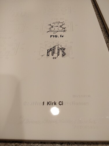
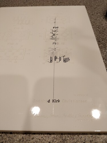
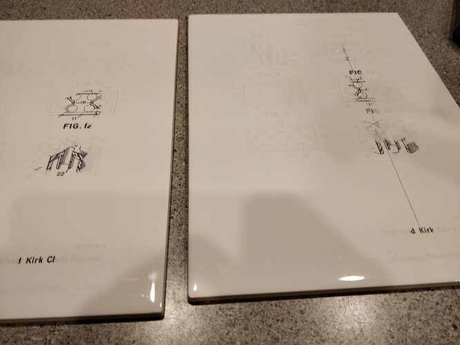
Lines in only some prints from the same file, same orientation

I recently have noticed random lines showing up in some of my engraves.

I have read that sometimes having open paths can cause this issue. I did get such a notification when I loaded my artwork and went to print. However, on the first print I had the long line artifact as shown in the photos, and the second print conducted immediately afterwards with material and nearly exactly the same position and same orientation did not result in the extra line being engraved.

I believe that I read if I create a raster or make a PDF and upload one of those files that this will not happen. The problem is that I didn’t see anything definitive on the subject, and frankly I don’t want to convert to raster because I think it’s just going to mean I’m going to have to fool around with DPI settings to get equivalent sharpness/results.

Can somebody please confirm that the same file engraving on the same size object in the same orientation only varying and location by a few millimeters and the x or y direction can result in an engrave that has random lines showing up in it like I have in my example below?

can someone confirm if I upload a PDF printed from the vector file (in inkscape for example) that I can be guaranteed this will not happen.

I can’t imagine running a test print on one material as a test and then putting somebody’s iPad or MacBook in the machine and having these sort of artifacts appear after previously getting a perfect print with the same file.

For those working in the mothership that may look into logs, these were the last two items printed 9/2/19. The first was printed with the defect, the second came out perfect.
It looks like what you are experiencing is a “random line” issue. The very short answer is it’s caused by either an open path/node or overlapping nodes. Two vectors stacked on top of each other will cancel each other out in the GUI. (Known bug.) So either the GF makes the line when it’s forced to close an open node, or two nodes on top of each other effectively trick the GUI into thinking there’s an open node and it tries to close them and you get the random line. (That’s my theory and I’m sticking to it lol.) Turning it into a raster will 100% fix it, or you can check for the above node issues. And yes, I totally agree it’s not consistent in how it occurs, it’s a huge pain in the arse and we shouldn’t have to deal with it, but it is what it is at this point.

A whole lotta other posts about it.
https://community.glowforge.com/search?q=random%20line%20order%3Alatest

4 Likes

The question is, does conversion to PDF fix the issue, or is the machine just unpredictable and inconsistent with vector format files regardless of how they are rendered on screen?

Fyi - I have observed this issue on prints that did not have open paths. I know that overlapping nodes can cause this - can we at least be notified?

I’ve had a mind-numbingly long day, and I work in technology, so I’m going to explain this poorly, but here goes… It’s not random.

At a guess, without really knowing anything about how the GF motion planner works, I’d say there’s likely a quantization error contribution to the variable outcome. The underlying math is probably standard floating point, which is actually pretty high precision. But the steppers only move in comparatively large discrete steps. Integer. The floating point has to be converted to integer someplace along the way to the final output. Depending on where that conversion happens, and where the artwork is relative to where the stepper can be, a vertex could end up on top of another, or it could be the next “step” over where it’s not aligned with anything.

By way of a simplistic example… make pretend it’s 1-dimensional positioning system (X) instead of 2 (X,Y). There’s a valid vertex at a calculated (based on the artwork) position of 2.6 and another at 2.4. These points have to be converted to an integer to correspond to a stepper motor step-to location.

Align the artwork with the physical motion control system so there’s no fractional offset between the artwork coordinates and the machine coordinates, position “0” in the artwork aligns with position “M” on the machine, M could be any integer number but it has to end in “.0”. To program the motion for the stepper, both 2.4 and 2.6 will have to be “quantized”, rounded down to an integer value corresponding to a particular “step” that the motor can realize. In this case, because there’s no fractional offset between the artwork and machine coordinates, they both end up with the same value, 2.0 (both 2.4 and 2.6 round down to 2.0).

But shift the artwork a little relative to the machine’s coordinate system, say by 0.5. 2.4 is still quantized to 2.0 (0.5+2.4=2.9 rounds down to 2.0), but 2.6 is now going to be quantized to 3.0 (0.5+2.6=3.1 rounds down to 3.0). The exact same artwork, but now the two points do not align.

The positional alignment of artwork relative to the machine’s coordinate system is for all intents and purposes arbitrary. There’s no button to align the upper left corner of the artwork with machine home, coordinates (0,0). You have no way of knowing where your art’s coordinates line up with the machine’s (to any degree of accuracy). So depending on where the art is placed, the outcome could vary because of the math.

[EDIT] as an aside, a “move artwork to home” button on the GFUI would arguably have some value…

8 Likes

I’ve never had any luck using PDFs and I avoid using them, but I don’t believe PDFs fixes it since the GUI still has to process the vector nodes. We use to have a preview window that showed how the GUI rendered the print and you could see the flaw before pushing print, but they got rid of it and I have not found a way to predict the issue. If I have an intricate engraving I always convert it now to be safe. It’s a pain to make a converted copy of the file, but I haven’t found a difference in engrave quality so the outcome is the same in the end.

2 Likes

That is incredibly disappointing.

Is there a published ‘limitations’ sticky/list somewhere that is an official register of these sort of quirks, or do we all need to make the same mistakes ourselves to self discover each flaw in the machine and then come here and find out that we are also suffering from the same design defect in the software after wasting hours and materials?

2 Likes

No, no master bug list. A lot of bugs are transient and update specific. There’s an update, a bug will pop up that we point them out to GF and the bug gets fixed. The only other bug that has been a constant and hasn’t been fixed is the “winding” rule. It seems to mostly occur with Corel users, but just recently it has popped up with other programs as well. (Affinity Designer I believe, maybe others as well) . I’m a Corel user and this bug causes me all kinds of grief. I know how to deal with it, but I shouldn’t have to.

There may be other constant bugs, but this is the only one I can come up with. Hopefully other will chime in if they can think of others.

2 Likes

I’m sorry for the inconvenience. We’re seeing this, too, and we’re looking into it.

As @kittski mentions, the issue can usually be resolved in the design file, or by rastering the design.

That’s a great idea for a feature - thanks for the suggestion! We haven’t announced anything like that yet, but I’m going to send it to our product team with a note that it came from a customer request.

I’m going to close this thread - if the problem reoccurs, go ahead and post a new topic. Thanks for letting us know about this!