I’m cutting boxes from rectangles of hardboard, MDF, and ply. I wanted to keep it simple to line up the blank with the no-cut zones in the UI.
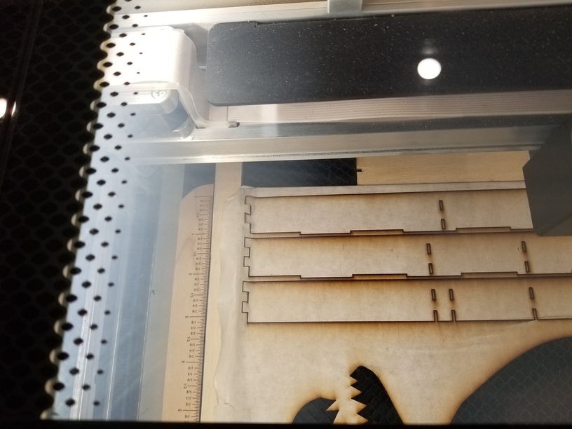
I figured out that the left offset from the raised part of the crumb tray is about 16mm, and 38mm from the top. I cut rectangles of scrap to 18xN and 40xN. Now I can drop the blank in up against the scrap rectangles and be sure that when I nudge the cut lines up against the edges (where they turn grey) they will be cuttable (according to GFUI) and on the board (because the board extends 2mm beyond).
For thin stock you can remove the wood and use holddowns after registering the blank.
The beauty of this is that I am not using the camera to judge the edges so the parallax is not an issue.
Incidentally, the right and bottom are about 8mm but I haven’t tested carefully.
0ne thing I just discovered today is that the available distance gets smaller on thicker materials. I very carefully marked out a maximum of 16 - 3.25 inch circles on 0.125" plywood and laid some 0,175 leather on top and could no longer engrave most of them with the thickness at 0,3"
And yes I keep a stack of long parallel scraps that will keep most large sheets locked in on three sides and then use magnets at the top wherever that lands so I can even remove the sheet and put it back exactly where it was.
Also, it will never be long before you have a pile of skeletons taking up a lot of space wherever they land with lots of those parallel sticks and chunks and squares that you are sure will be perfect for some small bit that you would certainly not want to waste a larger piece to use.
Faced with that problem and a new (to me) jigsaw I cut up all the skeletons and made three piles of larger pieces, small pieces, and those long parallel pieces noted above. the resultant piles together were not one 10th the volume of the skeletons they came from
.
As @palmercr just said, if you notice the available space getting smaller in the camera view it is because you have not set the material thickness correctly. Notice the rulers at the top and left sides of the image. The actual distance does not change with material height, just the view. Set the proper material height and the view is adjusted.
Still, a design with engraves will have a smaller bed limit than a design with only cuts. And speed is a factor. The bed limit is both a physical and a S/W function. The bed space limit is set to allow sufficient room for the head to slow down during an engrave or other fast movement avoiding the physical limit.
That sounds good in print but my experience has varied from that. I did a design with a circle around it and laid it out pushing the limits with engrave on and got 16 circles. Then I laid the leather I intended to engrave on the circles so the engrave on each would be centered then I changed the thickness to that of the plywood plus the leather laying on top of it. The lens then refocused to the combined height and 11 of the circles were over the engravable line.
Don’t know what to tell you. Not one to care whether anyone thinks I’m right or not. But there is something you don’t yet understand with how the system works. I’m not sure what that is only because I can’t watch your steps. Just trying to explain how the system works after over a year of using it. Take it as trying to be helpful or feel free to ignore.
I’m going to assume you understand that the bed image has nothing to do with the bed design space limits which are set in S/W and part of the user interlace. The material height setting only affects the image of the bed not the design space. It is used to dewarp the cameras fish eye providing an approximate rendering for design placement. (The material height is also used to set a default laser focus but that’s not relevant to this discussion.) There is up to 1/4" error in the bed image from true. Some machines are pretty accurate, some are off by that 1/4" even with a perfect material thickness. You can not assume that the design placement is accurate using the bed image alone.
The usable bed size is a completely different animal. It has nothing to do with the camera or material thickness entry. For a standard cut the S/W limit is currently 10.95" x 19.45" (+/- 0.005") For the fastest engrave the limit is 10.95" x 18.05". That changes with the speed of the engrave. I just separately uploaded a rectangle of those sizes for both a cut and then an engrave. Using 0.01" or 0.5" material thickness the placement within the design space or the usable bed limit did not change.
You can even test the bed limits without the GF being powered on.
What you are saying was indeed my expectations But when I laid the leather on the 1/8" plywood and aed posted the new combined thickness everything that was near the edge was now over the edge and was refused to print, so I ended up cutting holes and putting the leather under the plywood.