Pretty sure that means auto-calibrate the tab depth for building frames and the like. So two pieces orthoganal to one another will fit with no protrusion.
4 Likes
That must be the most convoluted way I’ve ever heard anyone say “so tab A fits snuggly into slot B”. ![]()
10 Likes
I would like to know how this is going to be implemented. I’m curious but am not betting the farm on this function. Where in the user interface would this show up? The CAM aspect is opaque to the user as to motion planning.
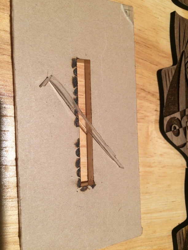
In any case, I did some of my own compensating for the kerf tonight. I cut a slot that was just a smidge too small to put a piece of acrylic into a slot. I took a little too much off of the size of the rectangular hole. So I resized the box to be .007 inches wider and higher for the next iteration. But before I cut the new piece, I stuck the box over the existing hole and nudged it over to take a slice off of one side and on edge. I took off a .45 mm sliver of acrylic off the .215" acrylic.
Pretty precise in positioning right under the head and once you know your material kerf sizes, dead on.
5 Likes
Well in CNC you input the tool diameter to the CAM program so I expect a kerf parameter to play with along with the power / speed as it would probably be different at different powers and speeds.
I can work around it not being there for my own designs as it is easy to do in OpenSCAD, but without it using the same SVG for different materials is not going to be possible where a close fit is needed.
It is a straightforward thing to implement compared to some of the other missing features so odd it isn’t there after all this time.
On the other hand adjusting tab lengths to match sheet thickness doesn’t seem straightforward because it has to identify what is a tab somehow unless there is some way to mark them in an SVG.
5 Likes
I’m pretty sure that Onshape has a FeatureScript that can automate that process in the design phase. It exports DXF files,and not SVG, though.
1 Like
Yes it is easy to do at the design phase with any parametric CAD but you need to measure the thickness and regenerate the file. Glowforge claims to be able to do that at the CAM stage but that is a lot more difficult because you can have a variety of tab shapes such as dovetails self locking tabs and possibly other random design features that depend on the sheet thickness, e.g dado slots.
I can’t see how it can auto detect these features, so presumably you would need to identify them in the GUI, which could be tedious and error prone, or annotate the SVG somehow.
3 Likes
A great tip! 
2 Likes
I believe (but have not confirmed) that the Onshape Featurescript takes into account the material thickness when it generates the tabs and slots. You would have to modify the original Onshape CAD file if your material thickness changes, but that should be as simple as changing the value for the thickness in the CAD file.
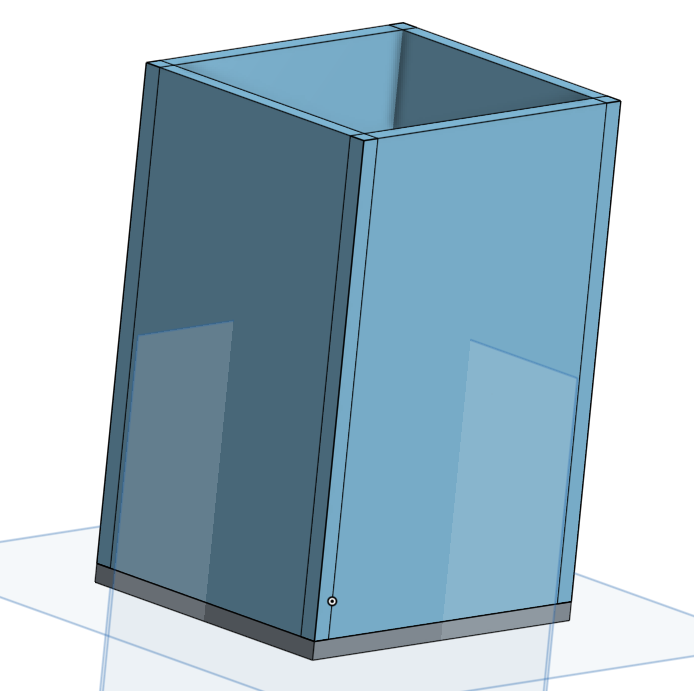
The aspect of the Onshape Featurescript (FS) that I find useful is that create the skeleton of the box (say) with overlapping sheets of material:
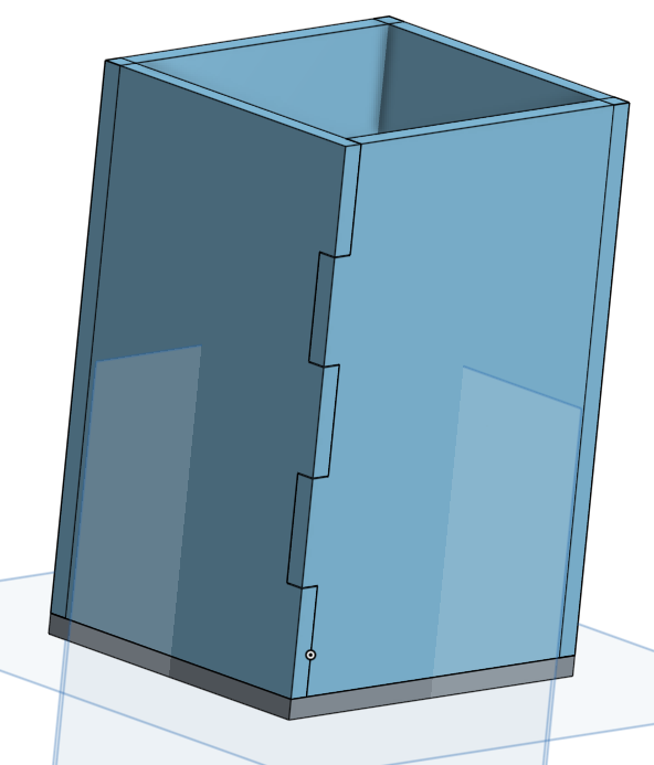
and then apply the FS to whichever faces you want to box joint. The FS then calculates where the tabs and slots should be placed and adjusts for the kerf value that you selected when applying the FS:
Here’s a closeup to show the 0.008" kerf that I applied in this example:
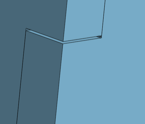
I’ve only done one edge of the box, bit it is easy to do all of them.
5 Likes
What’s been your CAM workflow from OnShape to laser compatible file? I haven’t found a great way to get complex 3D shapes out (exporting sketches is easy).
2 Likes
I don’t have a laser yet, so haven’t developed a workflow yet. That said, in Onshape you can right click on the face of a part in a Part Studio and Export to DXF from the resulting drop down list, so that’s I expect to use that workflow in my cutting and/or engraving. I expect to do a lot of these and that’s one reason why DXF import into GFUI is important to me as is the capability of importing multiple DXFs into one GF cut or engrave file. I know that the DXF(s) can be collected into an AI, Corel, Inkscape, or Affinity Designer file and exported as SVGs from there, but that adds unnecessary steps to my mind and means that both DXF and SVG files need to be archived for the same GF project unless they are just one-offs.
@dan - please move DXF imports up on the hopper priority list ![]()
3 Likes
YES, at this point it would be the single best thing your code crew could do for us. I’ve been asking and as a pru holder I know it would be a big time saver for anyone using any type of cad.
3 Likes
Yeah, that’s what I’ve been doing (and then pumping through AI to convert DXF to SVG). I didn’t know if there was something better (via the app store) like Fusion has which makes a more coherent laser file export. My 3D printing workflow is so mature at this point via OnShape I haven’t dove into laser output yet.
2 Likes
I’m just going to throw this out there, because I found it to be a somewhat interesting product…
I could have done some design work based on mechanical drawings in Fusion 360, but frankly sometimes F360 is just such a resource hog I hate it.
If you have Windows 10, there’s an app called Wedge which is a 2.5 CAD package. It’s actually not a bad lightweight parametric CAD, and it even does saves as either SVG or DXF (and imports DXF too). It’s free and might be worth a look for some people, anyways.
13 Likes
There is this 3rd party app for nesting which might be useful, but you’d probably still need to do the DXF=>SVG conversion.
This one lets you create separate slices from a solid part, probably something like that globe made out of discrete slices of corrugated cardboard in one of the GF intro video from 2015.
and it’s free.
1 Like
I tried the original code in openscad and the svg output is only 5 inches long. Any ideas? defaulting to mm instead of inches maybe?
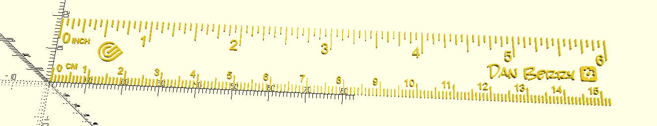
If you run the code, unedited, it should be a 6-inch 152 mm ruler.
Are you trying to produce one of a specific length?
- Or are you saying that the physical size showing in GFUI is depicting a 6-inch ruler in 5-inches of space? (ie.- a scaling issue)
1 Like
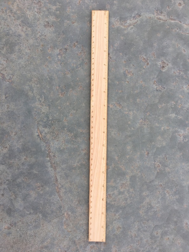
The original unedited one ( w/bling  ) Sorry I was talking about the 17 inch earlier. But the original 6-inch ruler shows up in the GFUI as a little over 1.5 inches in length
Around 3.8 appears to be the ratio
Well to make a 17" ruler with my original code, all you need to do is change “W” this code:
// RULER DIMENSIONS TO CREATE
// I recommend NO LESS than 3/4-inch high for 6-inch wide rulers
// and NO MORE than 1+1/4-inch high for 12-inch and longer rulers.
W=17; H=1+1/4;
RulerWidth = in2mm(W); RulerHeight = in2mm(H);
What version of OpenSCAD are you using?
1 Like