I’ve got digital angle tools that go to 0.05d, send me a file and we’ll check it out.
3 Likes
This is what I use for calibrating 3D printers.
l = 120;
w = 20;
rad = 0.5;
$fn = 32;

module L()
    offset(rad) offset(-rad)
        difference() {
            union() {
                square([l, w]);
                square([w, l]);
            }
            translate([w / 2, w / 2])
                square(w / 2, center = true);
        }

L();

Orthogonality can be checked with a try square.
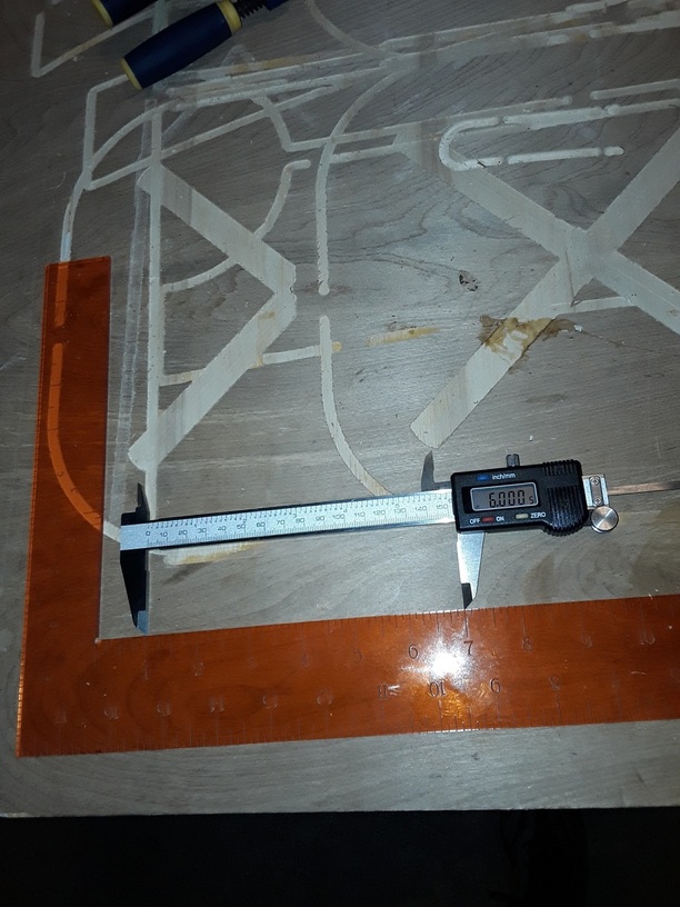
The inside length of the L is 100mm and is independent of filament width, or kerf in this case. On a laser cutter it should be a measure of the linear distance the head moves. On a 3D printer plastic shrinkage also affects it.
If Glowforge had kerf compensation as advertised the outside dimensions should be 120mm and the hole 10mm. At the moment I would expect them to be off by the kerf, enabling it to be measured.
The outside corners are rounded slightly to avoid any bumps when 3D printing due to stopping, allowing a more accurate measurement with calipers.
5 Likes
I don’t do open Scad but there is enough information that is human readable to do this and I will tonight.
2 Likes
You can download the svg which appears as a picture. I think it should work in the GFUI because it is just outlines with no fill.
2 Likes
I am sure you folks know this, but squares are straight forward to test if you have a few simple tools.
Here is a fairly straight forward example.
5 Likes
Darn. Now I need a granite surface plate and a couple gauge blocks. Do have the dial indicator though.
http://woodgears.ca/squares/index.html
Here is my design of a square that will fit into the Glowforge usable bedspace in one operation. Open to suggestions as to improvements or things I missed.
My goal was to have a light sturdy square to be able to easy dimension material to fit into the bed, like cardboard or plywood. I do have metal framing square, but thought it would be nifty to make one of my own. Since I have so much 1/4" acrylic.
Should work out with the kerf size. This was done in Inkscape using its tortuous tiled clone tool. Finally forced myself to figure it out. It positions in relation to the dimension of the object by using percentages. Not intuitive, at least for me, but ok. You do have to make the sets of different tick sizes in several operations. Still looking for an easier way. OpenSCAD definitely is easier. I’m sure that Inkscape’s scripting features could do this a little more automatic. In any case, it gets the job done when I’m cutting up cardboard.

20 Likes
you are way ahead of me on that one in Inkscape, didn’t even know what a tiled clone tool is and wouldn’t know how to find it. SO 
First off, thanks to @marmak3261 for the square file, it is going to work great for GF work.
These will not satisfy some of you as you are looking for mill accuracy in a prosumer laser cutter. I am satisfied myself. Like my handibot, know your tool and what it is capable of and what it is not capable of and work accordingly.
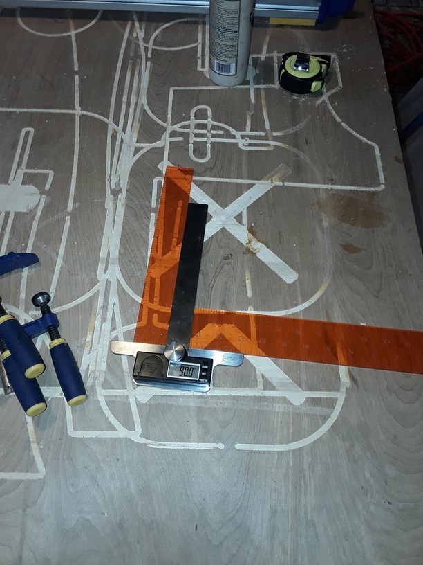
19 Likes
That’s so cool to see in the orange. How did the kerf turn out? Does it zero out at the corner? With all the 1/4" acrylic I have, I could make a slew of these. Need to make some triangle squares and smaller ones to use up the rest of the sheet. And there is still more of this acrylic to pick up in St. Louis!
1 Like
It’s 1/8 “fluorescent” orange from inventable’s. I can see myself using a lot of fluorescents as they look great and the engraving is quite readable without any inking.
As far as I can tell everything is dead on.
5 Likes
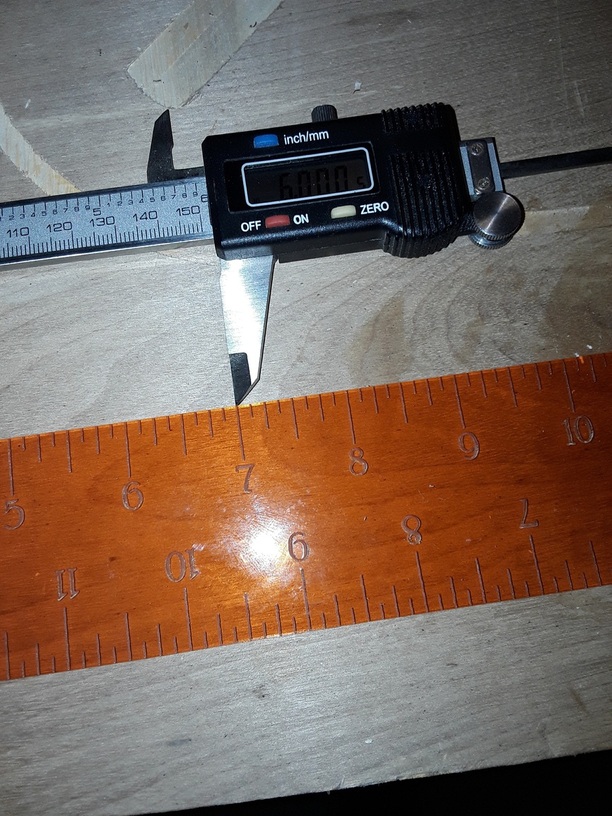
The fluorescent stuff is perfect for rulers! If you reverse the image and score it on the bottom you can avoid refraction annd paralax problems.
13 Likes
Holy cow. I never thought of that. Thank you so much! Now I’ll print my fourth sqare! This just keeps getting better.
3 Likes
@markevans36301 and @marmak3261,
Thanks for the doing this work. Am I correct interpreting the pictures as the linear dimensions are a bit off but the axes are perfectly orthogonal?
Since I only design in OpenSCAD I can easily apply correction factors as long as it is repeatable. I need to get a digital angle measuring tool though.
1 Like
My eyes are not nearly as young as they once were but I read it as dead on both ways.
2 Likes
It is as accurate as my steel roll tape measure as to the spacing of the ticks and lengths with the zeros starting at the edges or corner. The ticks on each side don’t correspond across the ruler because the full length of the sides are not whole numbers. That is purposeful because I wanted the measuring to go around the edge when turned at angles. It’s always a trade off in measuring left to right or right to left.
2 Likes
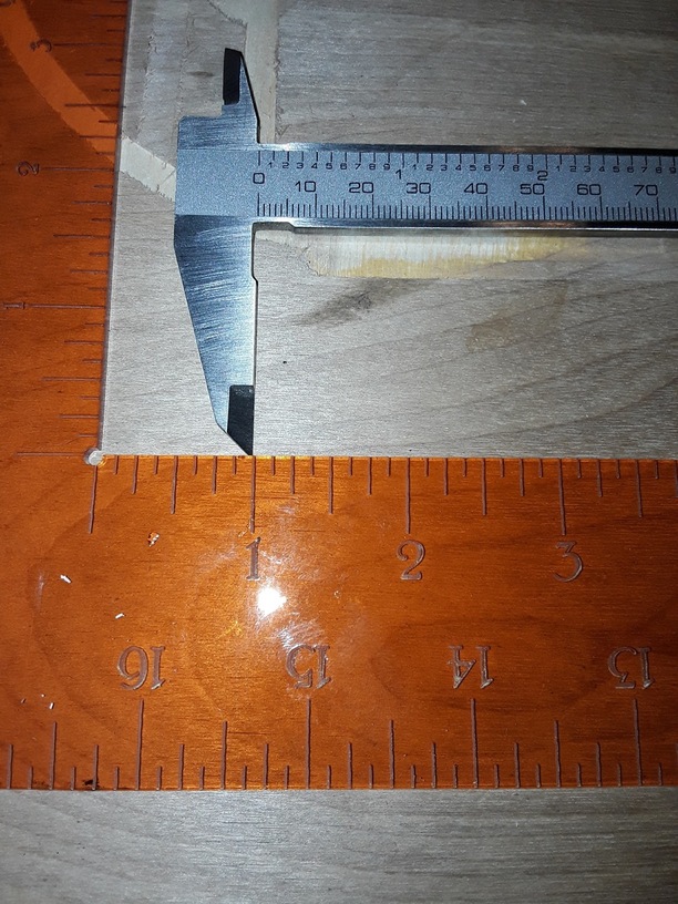
OK, so your machine is spot on then. @jamesdhatch ruler looked off but that might be parallax.
I try to avoid measuring anything by eye, I calibrate by using calipers on the edges so the result is a number rather than a judgement.
1 Like
I never said it was spot on, just that any off is less than I can see.
I agree that contact is better but I didn’t see a way to do that with this file.
They do not have kerf compensation working so if something is dead on it is because you are lucky or know your material.
2 Likes
Not just materials and luck: being able to do the math for the design and adjust according. I wonder if this automatic adjustment for kerf really is about the trace function and not for designs. So choosing to cut inside, outside or on the line is definitely in relation to the trace feature and really has no bearing on the designs I am making.
What does it really mean?
3 Likes
If you measure the inside length of the L then the two kerfs cancel out so you get a kerf independent dimension. But you need an L that is smaller than your calipers.
3 Likes
It is standard for CNC machines as the kerf is usually several mm. You make a design file that is your finished size in CAD and then pass it through a CAM program that converts it into gcode to run the machine. The CAM program adds half the kerf to outlines and subtracts half from holes. Glowforge advertises it does the same:
9 . Precision within a kerf
The laser works by removing a hairsbreadth of material, called the kerf. Glowforge knows this and compensates, so if you draw two puzzle pieces, they’ll fit. Even better, the Glowforge can measure the material thickness so 3D objects slide together perfectly.
Although I have never understood the last sentence.
2 Likes