Continuing the discussion from Adjusting for Kerf in your Design Parametrically - Fusion 360:
After posting the first tutorial above, the issue came up in the comments of “How could you account for kerf and still save as much of your material as possible?” (It’s expensive - we don’t want to waste it.)
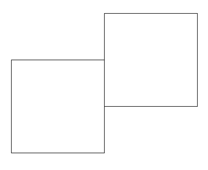
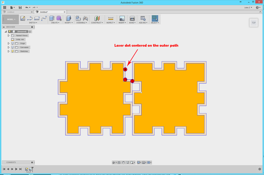
If you have two interlocking parts - as shown below, the most efficient use of your material is going to be a single cut, to separate the two parts.
But if you have to deal with a kerf, it’s going to nibble part way into each side of the cut line, which would damage your shape somewhat.
Now the kerf for the laser is extremely small - it will remove only half a hair-width from each side of the center line, and that might not matter enough to affect your design.
So if you are designing for laser, you probably aren’t going to want to mess with it.
This was really just me wanting to play with parameters a bit more, to see if it could be done. ![]()
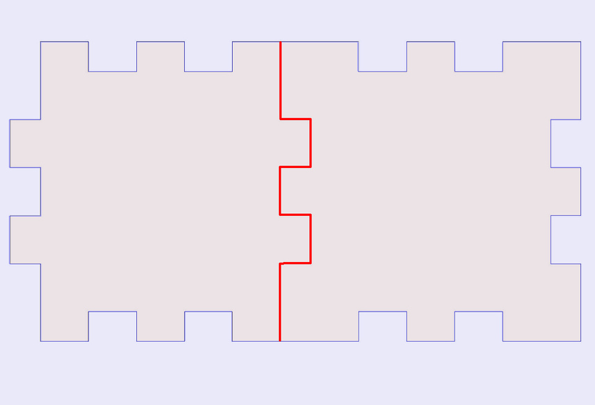
For the purposes of the demo below, i had to use a kerf of 3.0 mm, otherwise you wouldn’t see it.
That is NOT what the Glowforge is going to do.
(end of disclaimers) ![]()
Okay you’ve got a sketch in Fusion 360, and you have created your Offset relationships for kerf according to the original tut linked above.
So you already have the kerf variable created.
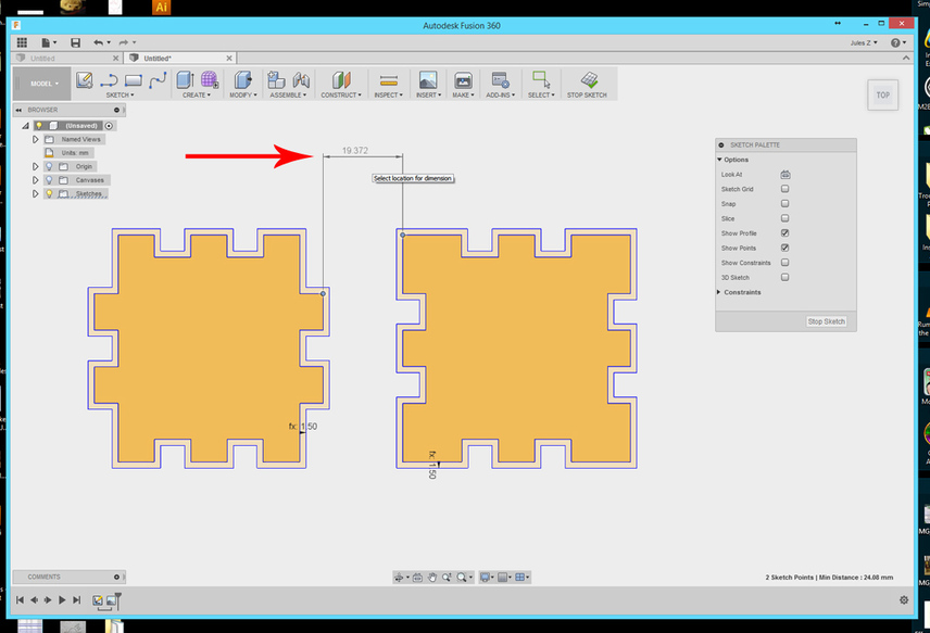
It’s very easy to optimize your parts placement by creating one additional dimension that connects the two closest points of the ORIGINAL shapes, as shown below:
.
.
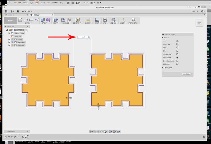
Set the dimension width to kerf.
.
.
The parts rearrange themselves to make the most efficient use of the material, while still honoring the kerf offsets.
.
.
.
One note: This placement will continue to change as you change the kerf, so it’s a permanent treatment for the file. If you don’t want to store your file that way, because it can be somewhat complex looking, you don’t want to just set the kerf to 0 for this dimension - it butts the two parts up against each other, and will keep them locked that way as long as the kerf formula is in that dimension slot.
You might want to change that one dimension back to 10 mm in order to space your parts further away again.
I’m not saying this type of optimization needs to be done, but it’s a good way to get a little more exposure to parametrics, which focus more on the relationships between parts than the actual dimensions of those parts.