Firstly, My Glowforge Pro is out of warrantee.
I need to replace my air assist fan because no matter how many times I clean it it sticks, runs slow and just ain’t doing its job.
I purchased a replacement fan from Amazon.
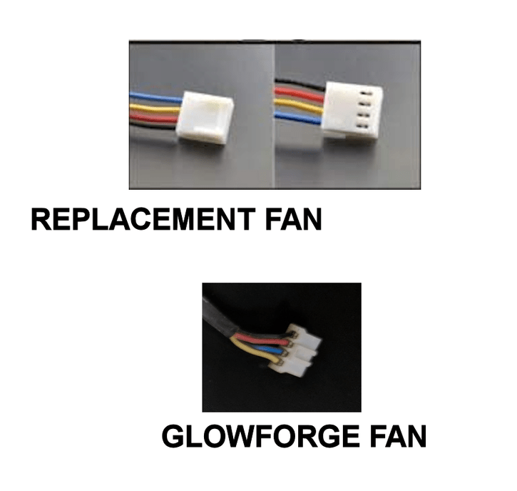
My question for anyone who has actually replaced their fan… I plan on using the original connector by snipping the wires and soldering the new one in its place. As you can see from this photo, the color coding on the new fan wiring ( see yellow and blue), are swapped. Which should I follow? Color for color - or - position of the wires (blue pin 1 or yellow pin 1)?
1 Like
I don’t have an answer, I just wanted to sympathise with you - such a frustrating problem.
2 Likes
give it a try, you may have to shave off the ribs on that connector. plug it in so that black goes where the old black went and red goes where the old red was located. if it does not work, switch the yellow and blue.
or…use the old connector, just cut the wires and solder it onto the new one. same plan: if it does not work, swap yellow and blue
3 Likes
Follow the position. Always follow the position.
I sell spares, including the correct connector housing and terminals for the Glowforge, so I’m used to making these connections. If you don’t follow the correct wire position, your fan speed will not register correctly and you’ll receive errors that will keep the Glowforge from operating.
3 Likes
Thanks for the info. If I follow you correctly, yellow from the new fan would go to “pin 1” of the old connector. Correct?
2 Likes
Correct
1 Like
thanks
1 Like
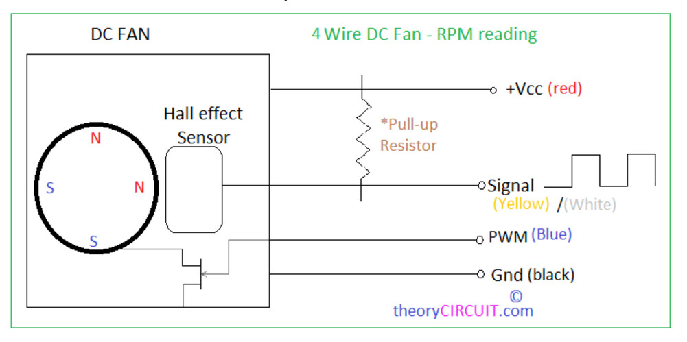
This is the likely air assist fan pinout. The Glowforge fan has a PWM speed control pin plus a speed sensor wire. If you can read a schematic you can see that the wire colors matter! ![]()
3 Likes
there actually is a gizmo(yes a technical term) that is out there that will aid you in changing the pins in the connector.
It shows up on my facewaste feed from time to time.
something like this…
2 Likes
Beware! Those pins may or may not be interchangeable between the two different plastic connector shells, but it’s worth a look. If you have a grinder or Dremel tool you can make your own pin removal tool by grinding down an Exacto knife blade to make it thinner. But that’s probably not needed if you look closely at the shell’s pin-retention scheme. An Exacto knife blade may be all you need to free the metal pin, which likely has a small spring tab poking through the slots on one side of the shell. ![]()

1 Like
Those pins are not compatible between housings. You will need to either get new pins for the JST housing that Glowforge uses or cut and splice the wires.
2 Likes
Thanks for all of the useful info, but if you read my original question, I’m planning on snipping the wires of the original Glowforge connector and splice the new wires onto the wire stubs coming out of the connector. I don’t plan on changing pins or connectors.
But thanks for all the info.
I realize that. I was just trying to show a tool that might make the whole task easier. 
1 Like