Came across this library trying to learn how to use OpenSCAD:
Any tips for a complete newbie would be greatly appreciated! Hard to wrap my brain around that stuff.
Came across this library trying to learn how to use OpenSCAD:
Any tips for a complete newbie would be greatly appreciated! Hard to wrap my brain around that stuff.
I think @palmercr is the OpenSCAD expert here. 
Wow. The author of the library goes from 0-75 pretty much instantly. And he’s missing some bits that would simplify design a lot. But it looks like a pretty good set of connecting methods if you already know openscad. I might use it or see if I can bodge it to meet my needs.
Basically, what you do is specify a flat sheet of whatever dimensions and then place various joining cutouts/tabs on or near the edges (also using text). Plus scripts for things like making boxes, which are basically just a bunch of flat pieces whose dimensions and cutouts are determined once you give the overall box dimensions.
Ironically, given that openscad is a 3D program and you need to make things 2D to export for cutting, the library doesn’t (yet) seem to be so good at helping visualize the assembly process. That could be fixed, though (there are other openscad libraries that let you say essentially “this edge of this piece is connected to that edge of that piece, now rotate them 90 degrees with respect to each other” and get two piece fixed together with a right angle between them, without a lot of numbers.)
Yeah, I’m having trouble using the library that’s supposed to make life easier. I don’t already know OpenSCAD. I got this far:
So I don’t feel too bad. I can’t get it to lay things out flat automatically, though. I don’t exactly know what I’m doing.
Edit: and it looks as though something with OpenSCAD or something with trying to get the library to lay things out flat has deleted all of that work.
can you post your file? (Or is that what’s gone?). What you have looks pretty good as a start.
It was gone. I’m going to try building it without that library first to get a little more familiar with OpenSCAD. Here’s the current file so far:
thickness=3.1;
height=30;
x=250;
y=80;
for(dividers = [x/6 : x/6 : x-(x/6)])

color("Gold",0.5){
    cube(size = [x,y,thickness]);
    rotate([90,0,0]) translate([0,0,-thickness]) cube(size = [x,height,thickness]);
    rotate([90,0,0]) translate([0,0,-y]) cube(size = [x,height,thickness]);
    rotate([90,0,90]) translate([0,0,0]) cube(size = [y,height,thickness]);
    rotate([90,0,90]) translate([0,0,x-thickness]) cube(size = [y,height,thickness]);
    difference() {
        rotate([90,0,90]) translate([0,0,dividers-thickness]) cube(size = [y,height,thickness]);
        translate([10,10,5+thickness]) cube(size = [x-20,y-20,height-10-thickness]);
    }
}
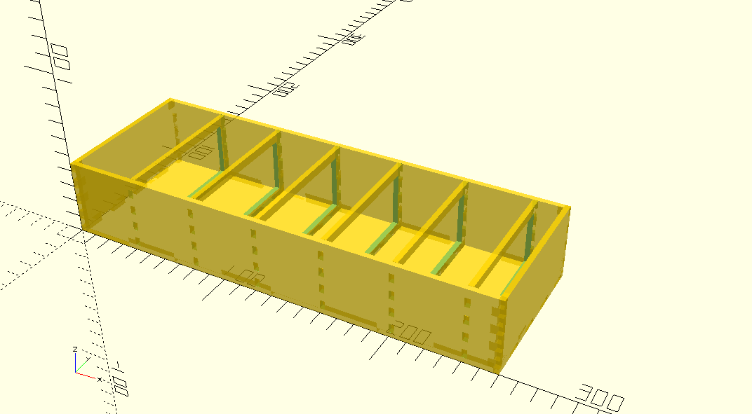
And the results:
I haven’t subtracted out the part to make the tabs and I need to figure out how to add a smaller section on one end to house my ultrasonic sensor and a little Arduino (see this post for where this project is coming from.)
At this point, it seems to be parametric as I understand things. I can change the variables at the top and the design still looks good. Yay!
Nicely done! I’m going to make one style suggestion that can be useful sometimes, namely to consider making your cubes with center=true (it’s added to the cube descriptions after the size: cube([xdim, ydim,zdim], center=true) ). Sometimes it simplifies the arithmetic, because you don’t have to remember that the default cube is all in positive xyz, while cylinders and spheres are mostly centered on the origin by default.
Thanks! I’ll give it a go.
@paulw, you look like a bit of an expert on OpenSCAD as well, do you have any tuts to recommend? (Or are you working on one on the Training thread?)
I’m slowly building my own OpenSCAD libraries. I did not look at the project in the initial post, but based on paulw’s description of it I’m taking the same approach. A joining library, a panel library, etc… I am deliberately not using the force (other people’s code) because doing it myself is still forcing me into a deeper understanding of the tool. Also, I have options for kerf and material tolerances. That is not to say that at a future date I won’t incorporate what others have done.
As regards the programming language/development environment - it is very basic.
As for learning it I just started by coding a joined box. Then I refactored it with their idea of functions and procedures. Then I made something more complex with curves (the glowforge logo.) Now I’m writing the libraries for a system that when finished should make designing something new a challenge in design and not in coding.
I’ve tried at least two of the popular 3D programs mentioned a lot here, but I just get frustrated with their mechanical engineering approach, instead of a software approach, to mechanical design. I curse at the computer a lot, ask it why it’s so dumb, and then go back to OpenSCAD where things are slower but where I am comfortable.
It’s not everybody’s cup of tea but as a retired programmer it suits me down to the ground and I now code objects instead of algorithms.
I also construct all my own libraries because I enjoy writing code more than using other people’s.
If that means you have the time, then that’s what I need: time. I do enjoy it.
The first three tutorials at the openscad site are pretty decent iirc. I’m thinking about doing a simple tutorial on reducing 3D to 2D, which might be particularly useful for zapping.
That would be fantastic! 
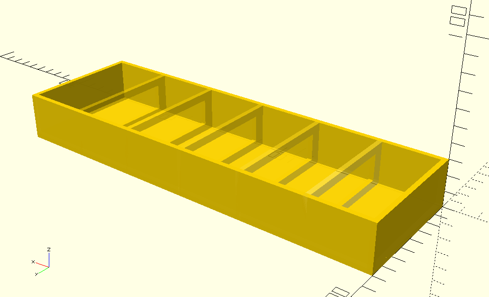
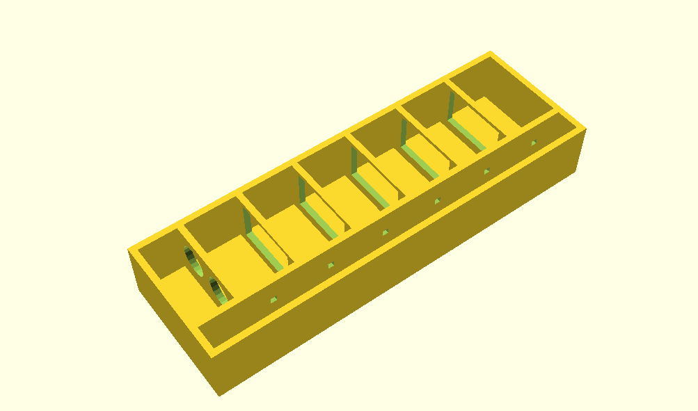
Here’s an updated version of this project:
So, I went back to using the lasercut library and was confused with using “center” and this is the result. I did some wacky things early on, but I think I got most of them out when I was changing numbers to see if it was parametric. Still to do, add a couple of more slots and put lids on the sensor compartment and the LED compartment and add an opening between them for wiring. Here’s the mess of incomplete code with my appologies:
include <lasercut/lasercut.scad>;

thickness = 3.1;
height = 30;
width = 200;
sensorcomp = 25;
ledcomp = 15;
depth = 50+ledcomp;

color("Gold",.75) {
difference(){
    rotate([0,-90,0]) translate([0,0,-width]) lasercutoutBox(thickness = thickness, x=height, y=depth, z=width, sides=5);
    rotate([0,0,270]) translate([-ledcomp-thickness,-5,height/2+thickness/2]) lasercutoutSquare(thickness=thickness, x=thickness, y=width+10);
    //add slots for dividers here
}
difference(){
rotate([0,270,270])translate([thickness,thickness,ledcomp])lasercutoutSquare(thickness=thickness, x=height-thickness, y=width-thickness*2,
    simple_tabs=[
            [UP, height/2, width-thickness*2],
            [DOWN, height/2, 0]
            ]
        );
    //add slots for divider tabs and led holes here
        for(dividers = [sensorcomp-thickness : (width-sensorcomp)/12 : width-thickness]) translate([dividers,ledcomp-thickness/2,height/2+thickness/2]) lasercutoutSquare(thickness=thickness, x=thickness, y=thickness*2);
}
{
difference(){
        for(dividers = [sensorcomp : (width-sensorcomp)/6 : width-thickness])
        rotate([0,270,0])translate([thickness,thickness+ledcomp,-dividers]) lasercutoutSquare(thickness=thickness, x=height-thickness, y=depth-thickness*2-ledcomp,
    simple_tabs=[
            [UP, height/2, depth-thickness*2-ledcomp],
            [DOWN, height/2, 0]
            ]
        );
translate([sensorcomp+5,ledcomp+thickness+5,thickness+5]) cube(size = [width-sensorcomp-thickness-10, depth-ledcomp-thickness*2-10, height-10]);

        rotate([90,0,90]) translate([sensorcomp+depth/2-thickness*2,height/2+thickness,sensorcomp-5]) cylinder(h = 10, d = 15);
        rotate([90,0,90]) translate([sensorcomp+depth/2-thickness*2-20,height/2+thickness,sensorcomp-5]) cylinder(h = 10, d = 15);


}
}
}Looks plausible to me, as far as I can read it. Just one style/method comment: you may find it less brain-exploding to do your translates after your rotates. When you translate first, your object still gets rotated around [0,0,0], which means it moves as well as rotating. It’s not such a big deal working in multiples of 90 degrees.