What is an acceptable cut variation between x and y coordinates? For example, I keep cutting squares, but they come out as rectangles. I spent the last hour or so reading forum posts with similar problems, but I just needed to know if my results are normal. Usually there’s a variation of 0.05mm / 0.002" between x and y axis cuts. A 20mm x 20mm square comes out as 19.87mm x 19.92mm (X x Y). I tried rotating the wood piece 90 degrees to change the direction of the grain, and the results were similar. I even tried rotating the square 45 degrees so it cuts like a diamond, and I got similar results (variation of 0.07mm). The piece of wood was perfectly flattened with magnets. The machine is perfectly square. I manually moved the gantry as far back as possible before starting, to ensure it’s square. Both x and y belts appear to be tight.
I’m cutting 1/8" baltic birch by the way.
If this is considered an acceptable variation between x and y, how can I use these numbers to accurately calculate kerf? If I went based on the ‘x’ results, I’d get a kerf of 0.065mm. If I went based on the ‘y’ results, I’d get a kerf of 0.04mm. Can someone provide any insight into this?
What speed are you running at?
Stepper motors can lose steps at higher speeds, if you are running at very high speeds it’s possible (though fairly unlikely) that you’re seeing that.
As for your discrepancies between measurements, if something is wrong, I suspect your kerf is consistent but that the laser placement is off.
That being said, I am not convinced that you actually have a mechanical problem. You’re reporting a discrepancy of about 0.05mm, which is right about 0.002", which is pretty tight. I don’t know how you’re measuring things but 0.002 is just about the margin of error with most calipers, your technique and equipment matter a great deal at that stage.
Also, bear in mind that the cut profile is not perfectly orthogonal, so measuring the top or bottom of the cut material will yield different measurements, and 0.002" would be easily explained there.
So, in short, I’m saying that in a real world situation, 0.002" accuracy is probably well within margin of error of your measurements. I don’t know what material or settings you’re using, those will both impact kerf a great deal more than 0.002".
The machine is spec’d to 1/1000th. Kerf for most materials is 3-4 times larger than that.
You’re chasing precision the machine was not designed for.
I’m running at 200, full power to cut baltic birch plywood.
Yeah, I made sure I was measuring along the widest part of the square for that reason.
I’m happy with the level of precision and I can certainly live with a precision of 0.05mm. My main question was how to accurately calculate kerf considering cuts are different on the x vs the y axis. It seems finger joints cut along the x axis will fit slightly differently from finger joints cut along the y axis. But if you guys don’t think that much variation between x and y will affect the kerf noticeably, then I trust you. I’m still fairly new at this.
Thank you.
What kind of material? If it’s hardwood, I’d say grain direction probably comes into play.
If you want to rule out an actual physical glowforge problem, maybe try cutting at a 45 degree angle, see if you get a difference there. In theory, it would equalize the discrepancy and you’d get a more uniform fit.
You say “finger joints”, this is across multiple designs? If it’s one design, have you gotten really accurate assessment of the design itself? Like maybe the problem is in the SVG? If it’s lots of designs, were they all generated by one box maker or something?
You may have some issue, it’s hard to say. I’m not trying to tell you you’re wrong, it sounds like you’re being pretty methodical, you might be onto something.
The reason it’s not going to matter is because the actual kerf is so much larger than the imprecision you’ve noted. After testing multiple materials (acrylic, hardwoods and ply), I’ve found .1mm is sufficient for all of them, at least for what I’ve done. There is so much variation in even the same piece material, it’s not worth trying to get closer.
TL:DR - I have a couple of 0.001mm micrometers - Swiss made by Tesa, my father was a toolmaker. When I first started understanding kerf, I thought it would be cute to measure with them. Variation for each “identical” part from the same sheet is so significant, it was pointless. My Mitutoyo calipers are precise enough to show the variation.
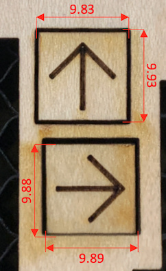
I just printed two 10mm squares adjacent to each other, rotating the material between them. The arrow points towards the rear of the machine for each cut. The lower one in this image was cut first. Proofgrade Medium Maple Ply. Mitutoyo 500-133U, measures to .01mm/.0005".
Dimensions embedded. One varies by .1mm x-y, the other by .01mm. That is my point. The precision is simply not there.
Good to know, thank you for the input. But just to add a final thing, my concern not specifically due to the variation, but the fact that it was consistent. This made me thing the machine is eerily accurate, but it seemed to be off by the same amount everytime (between x and y); y always being 0.002" longer than x. And if I can get it to read just 0.002" more on the y axis, I could get perfect squares everytime, and the evil laughter that rings throughout my house whenever a project emerges from the Glowforge would be even more warranted.
But I can live with a rectanglified square. I think. Damn OCD.
I get similar results as @malek1979m. I ignore the difference when calculating kerf and just base in on the bigger number. It is hardly noticeable. I get nice tight fits when needed.
This topic was automatically closed 32 days after the last reply. New replies are no longer allowed.