So what thickness/height measurement is being used where?

Yes, you can override the height Manually if you prefer to set your own Focal Point.

Or you can override it for just one or two parts of a file - for instance if you want to run a second pass defocused on your engrave to cleanup the ridges that lasering leaves in acrylic. Or if you want to Score something defocused to get a wider score line.

It’s kind of cool when it changes focus during a file, the machine pauses, the FP is reset, and it resumes. Freaked me out the first time it happened. :smile:

It’s going to use the surface auto-measurement for cutting unless you over-ride it in the Manual Settings, but as you probably know, there are a lot of reasons why you might want to change it. You can change the cutting profile by setting the FP in the center of the material instead of at the default top position.

If you want to take control of the FP, you can, for cases when you have something special to accomplish. Otherwise, I’d just leave it alone - they’ve done a really phenomenal job setting them for the PG stuff - there are really very few complaints about things not cutting through.

Heya thanks for that! I completely hadn’t thought of using a defocused pass to clean up the ridges … what does that kinda finish look like? Do you need to remove the paper before cutting for that to work?

Back to the question I had though, I think maybe you’re answering a slightly different question to what I’m asking.

I know you can override the focus distance to do things like defocusing the laser. From the previous discussion though, it sounded like the GF starts with the red dot (the autofocus sensor) and then applies whatever offset you’ve specified.

I want to know if it’s possible to completely ignore the autofocus sensor altogether if I’m working with a job where I don’t have confidence that it’ll give me a sensible answer (eg. because I’m engraving an oddly shaped piece of stock and don’t trust that the sensor will land on a surface that’s at the same height as the engraving surface).

1 Like

Ooh also an additional nugget I wanted to ask you about:

You can change the cutting profile by setting the FP in the center of the material instead of at the default top position.

So you can specify where the GF autofocuses? That would certainly make life easier (or at least give some confidence that it’s hitting the right spot) … how do you do that? I might have missed something there.

Pretty sure she’s referring to top to bottom surface, rather than an X Y position…

So if I tell it the material is 0.10" & override one operation to be 0.12" but the red dot laser measures it for the GF as 0.09" then my override is actually going to focus at 0.11" because that’s 0.02 over the actual laser measured height and not the 0.12" I specified?

And if I don’t override anything and I put in 0.10" for the height but it measures out with the laser at 0.15" it will use 0.15"?

BTW, how did you determine that? I had my PRU for 9 months and never noticed it wasn’t doing what I assumed it was doing. Although to be honest, I wouldn’t think the delta would matter except maybe to the OCDers.

My experience has been that you can tell it where to focus by going to the Manual settings and setting a Focal Point for that operation. It overrides the auto-focus. If it selects a FP of 0.15" for the entire operation, and you have an engrave on a section that is 0.18" tall, and you manually set the FP for that engrave to be 0.18", it will focus that engrave at 0.18", and move back down to any other operations that might be happening at 0.15".

Yes, I was, thanks! :wink:

I was basing it on this discussion, which I now realize I totally misundestood. I take it all back.

Shoot, I don’t know… ¯\(ツ)

1 Like

Okay. I think you’ve got it wrong then.

@Takitus said that it would use the FP entered in the operation - not the delta between that & the measured.

@Dan said @Takitus was right.

So based on that, if you tell it the material is 0.10" and override to say 0.15" and then the GF measures it to really be 0.08" the override is still 0.15", not the 0.13" your formula suggests.

That means it’s really defocused by 0.07" and not the 0.05" that I might be presumed to have wanted, but it is the 0.15" that I told it.

2 Likes

Too complex for my blood. Looks like they are applying more dewarpage (new word I made up :blush:) based on the red dot measurement as well. Might have nothing to do with setting the FP.

Pretty sure the FP is populated into the slots from the Unknown Materials height entry, or from the PG stickers. After that, we can set them to whatever we want. (And I frequently change them.)

Note: Just remember FP height is measured assuming the top of the tray is zero, going up. (I think.)

1 Like

Nope, I’m not saying anything.
images

You’re right – I’m wrong.

Damn, I 've used up my quota for 2018. :wink:

4 Likes

I would assume autofocus differs from material thickness because it’s meant to determine top surface height, not thickness: essentially it would be GF attempt to compensate for variations in distance lens-to-tray-top. you can easily measure your material with a caliper, not so easy to measure distance from material to laser…

Okay. I’m just happy to have a simple answer. The delta thing seemed way more complicated than necessary :slight_smile:

Any ideas how they derive the 0 point for each unit?

My crumb tray was pristine (no burns or scrape marks anywhere) and the initial image on my Basic was of the calibration jig. If all crumb trays are actually the same height, then why all the fuss about measuring their height for extra tall materials? Could it be the 1.4" +/- 0.002" variation folks are reporting actually be measurement error? That might explain why 1.4" always seems to work for me, although my el cheapo calipers insist that the top is 1.038".

OW!!! BRAIN CRAMP!!!

2 Likes

Ok, reading this thread is making my brain hurt. Not sure if it’s just me but I still don’t understand for sure how this works.

I thought for non-PG material we had to enter the thickness ourselves. Am I reading correctly that I don’t need to do this? That the red dot will determine this itself and fill in the number?

No, you need to enter it. That measurement is used for a couple of things, and if it’s not in there, you’ll throw an error.

And because I’m not actually smart enough for the rest of this conversation this is the part that’s hurting my simplistic brain. If the machine has a way to measure the thickness of the material on the bed that is more accurate than my cheap calipers, then why the heck do I have to do it. Why not have an option that simply says “calibrate” that sets the focal height Of the laser and goes back and fine tunes the camera distortion. Granted I could see the need for manual compensation where the head ends up trying to focus in the wrong place (say a cut out, etc), or it just goes a little wonky and needs your help, but considering how much material is sheet based I would bet it would work just fine a large percentage of the time. The. We would just have to compensate for uneven or warped materials. I’m sure I’m missing something, but from the cheap seats it seems like we’re unnecessarily chasing our tails to do what the beautiful Glowforge could do better itself :stuck_out_tongue_winking_eye:

3 Likes

I actually got this part right according to @dan – the thickness entered for non-PG materials is used to focus the lid camera display, thus allowing you to more accurately place materials and files. The further off the measurement is, the less accurate the placement.

Lidcam = placement
Red dot = auto focus, based on a single location.

4 Likes

I think a lot of people are confused about the thickness of the material versus the Focal Point measurement.

The thickness of the material information is entered into the Unknown Materials slot, and then that value is used to adjust the focus of the lid camera output to eliminate as much of the fisheye effect as possible, making placement on the material more accurate. If that value is not entered correctly, the placement alignment can be off by a LOT.

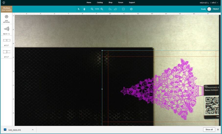
If you want to test it yourselves, put a design on the screen, and then change the material shown (using the list) from Medium Draftboard to Thick Draftboard. You can see how much the image you see moves. Mine is actually pretty well aligned, but first you can see the placement of the bottom of the tree against the sticker, with Medium DB selected, then when you change the Material to Thick DB (which it isn’t) you’ll see the placement appear in a different place. The larger the difference between the thickness of the material and what is actually in there, the more that placement is going to appear to be off of where it actually is. (Which is why thin paper and cardboard can be so far off - they are a lot thinner than PG materials.)

Okay, so that’s one thing that the entered thickness does, but the other thing that happens with it is the value is populated into all of the slots for Focal Point. The default FP on the machine appears to be a point either at the surface of the material for Unknown Materials, or just slightly below the surface of the material for Proofgrade Materials. (Reason for that I believe is to punch through the thicker veneer, but I’m just guessing…the default generally works perfectly for the PG materials, but it does seem to be set slightly below the surface. I measure the material.)

If that information wasn’t automatically populated into the FP settings slots, we’d have to put them all in by hand, which is a royal pain in the tush. If you put a Focal Point distance in the slots (because you can set a Focal Point at the base of the material, at the middle, or at the surface of the material, it is going to override the value loaded by the Unknown Materials height (again which assumes the FP at the surface of the material.) It’s because they use the surface as the FP that everyone is getting confused by this, but you can set your FP anywhere inside the material, or above it. What changes when you do that is how the beam (X shaped) is dispersed through the material, and you are going to see some incomplete cuts, wider kerfs on the top and/or bottom, and strangely shaped cut profiles.

And, I’m getting off topic. Sorry.

The red dot laser might just be correcting the warp for placement of interrelated parts of the designs, it’s not calculating the actual height of the material or inputting it into the slots for Focal Point. For all the machine knows, we might want to cut the thing out with the Focal Point on the bottom of the material instead of the top. (Don’t recommend it, it really makes a mess with charring, but I have tested it.)

This is one of those things where if we want to have the option to do other things with the machine, they need to let us set it. They make it as easy as possible for those who don’t want to mess with it by auto-populating all the necessary Focal Point slots with the value when we put it in one place (Unknown Materials Thickness slot), but I don’t always want them telling me where to set the Focal Point. (Call me a rebel, sometimes I want to go my own way.) :wink:

4 Likes

Thanks for this explanation. I think its cleared up the muddy puddle for me. Mostly, lol.

1 Like

When you enter a focus height it gets used and the red dot value is ignored. If you do this for all operations it still scans the material. This is what causes confusion that it might be offsetting
It isn’t. It is a completely redundant operation.

Things are different with PG settings. They can specify an offset from the red dot value.

It would be nice to use the red dot to measure material thickness but the issue is where it would measure because you haven’t placed the design yet.

We have no idea how accurate the red dot is because we can’t trust any of the specs. It currently sets the focus but that only has 15 0.7mm steps.

2 Likes