How tall were your dice?
Huh. I would have thought you guys had measured that when you were doing all the measurements around the head/lens focusing movements and range.
It would be a useful thing to know. I know the red dot laser used for positioning on the Redsail isn’t very precise so I wasn’t expecting much from it. I figured it was still in process. Didn’t realize it was doing any meaningful measurements.
well it’s supposed to eventually take care of the continuous focus, so it better be meaningful!
But the problem is that it is calculating material height. Let it measure in a hole in the material, or accidentally bounce off a magnet instead of the surface and you will see a definitive change in cut and engrave quality regardless of what you set material thickness to, unless you also set an offset on the step itself.
I understand that we put in a material thickness to let the machine dewarp the image and allow for more accurate placement. I’m just saying IF the red dot is actually taking a percise measurement of where the top of the material is, it would be nice if it would turn around and use that measurement to better refine the dewarping of the bed image, or better yet, When a new clean sheet of material is put in, just automate that whole initial process and let us start fiddling from there. I use offsets all the time, especially with engraves. I don’t want it to take away my ability to set things manually when I want, it just seems they have all or most of the pieces in place to simplify the initial startup and remove at least some user error (oops! Forgot to zero out my calipers!)
I don’t think there is a way to get at the measured value. My understanding is it sends an image of the dot to the cloud. The cloud calculates the height and then generates the motion file with the steps in it, never reporting the height. Since the steps are even multiples of 0.35mm, i.e. 0.7mm steps, there is no way to check the claimed 0.1mm depth measure accuracy and I don’t see how it is useful to be more than the focus resolution. The very low focus resolution is a big surprise.
1 Like
The dice were 16mm, so I put the jig on top of a piece of 3/4" plywood to get a final height of 0.02. The top of the jig was too low. I guess I could try and always make sure that my jig surface is at crumb-tray height or above, but that quickly gets to be a pain.
OK so to try and lay at least part of this to rest, I’ve gone and done an experiment.
I took a bit of ply (PG medium maple but without the PG QR code, the GF only knows what I tell it), 0.13" thick and propped one end of it up on three layers of ply making a wedge. One end being 0.13" thick, the other being 0.52" thick (plus a bit). I then engraved a single line up this wedge using a variety of settings. The idea is that I can tell at what height the laser is focusing by where along this wedge the engrave line is the sharpest. I used 100% speed, 50% power so all it was really doing was marking the paper but it also means I can clearly see when it’s not focused and petering out.
Here are the results:
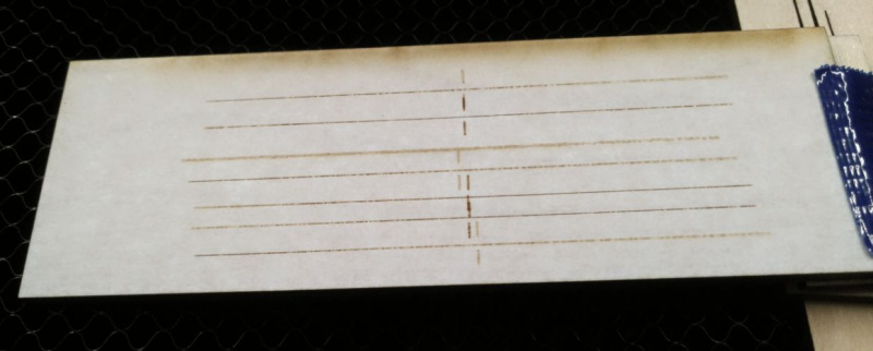
Here are all the settings of each of the lines.
- Thickness 0.5", Focus override to 0.13", Red dot was in the middle.
- Thickness 0.5", Focus kept at 0.5", Red dot was in the middle.
- (Initial test, messed up something else)
- Thickness 0.13", Focus kept at 0.13", Red dot was on the right 1/3.
- Thickness 0.13", Focus override to 0.5", Red dot was on the right 1/3.
- Thickness 0.13", Focus override to 0.5", Red dot was on the right 1/3.
- Thickness 0.13", Focus kept at 0.13", Red dot was on the right 1/3.
To me the interesting thing is the last four lines. Lines 4 and 7 are better focused to the left (ie. the laser is focusing around 0.13", where I told it to). Lines 5 and 6 are better focused to the right (ie. the laser is focusing around 0.5", again where I told it to). The red dot was measuring nowhere near 0.13" (where it hit the thickness would have been about 0.4" or so).
To me this suggests that there is no autofocus happening and it’s just trusting exactly what I write into focus height!
(Lines 1 is also also consistent with this observation … the left of line 1 is consistent with focus at 0.13", yet the autofocus sensor would have been reporting something like 0.3". Line 2 is a bit harder to explain, it looks better focused in the middle which would be around 0.3", same as the red dot point.)
A secondary interesting thing is that for the same file there seems to be little consistency as to where on the job the red dot scan is being made (for some it ended up right where that crosshair was, in others it was about 1/3 from the right end).
What do you all think?
I think that plays into the observation that if the operation focal point matches the material height manually entered, then it uses the red dot. If the focal height in the operation differs from the material height entered, it ignores the red dot reading.
Two questions on this topic:
- if you do a manual cut with two or more passes, does it automatically change the focus height for each pass? This would be like a CNC router doing multiple passes with each one at a different depth.
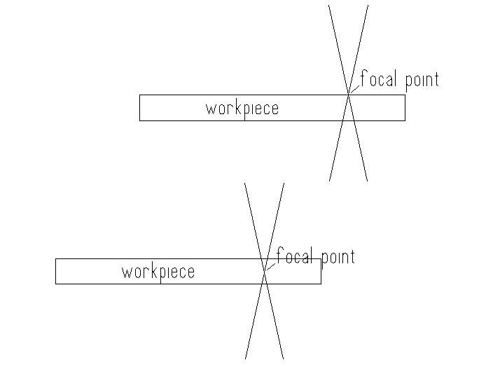
- if you move the focal point from at the surface (top image) to be partway through the material, (second image) does it behave like the crude sketch I am attaching here? This might not make a big difference for thin material, depending on the angle of the beam, but would make a difference for thicker materials.
I’m not so sure that that’s the case … when you say “the operational focal point matches the material height”, those would correspond to the lines where I say “focus height kept at ___”.
If what you say is true (ie. if I keep the focus height the same as the thickness then it uses the focus sensor) then I would expect lines 4 and 7 to be sharpest where the red dot was (in the right 1/3 of the line). Whereas in fact they are sharpest at the other end.
I don’t know the answer to question 1 … I mean it’d make sense but on the other hand the cone of the beam still needs to get through the kerf at the top. I guess you’d get better efficiency at the bottom of the cut but you’d also lose power as bits of your beam hit the walls of the kerf so it might not be worth the trouble at these thicknesses.
The answer to your question 2 I believe would be yes. While it probably wouldn’t make much of an efficiency difference, I have played with other laser engravers (generally with thick materials like 10mm acrylic) where it does change the quality of the cut edge a little (eg. how straight the kerf is) so depending on what you’re doing it might be worth messing with this.
Not currently.
The math is done in the cloud, and the only evidence of the results are the number of steps for the Z axis in the resulting step file.
The electro-mechanics are capable of 0.35 mm increments. As @palmercr has pointed out, the Z steps are in multiples of two for some unknown reason. This means the current focus is done in 0.7 mm increments.
So, they could claim a precision of 1 million decimal points, and it wouldn’t mean a thing because the best resolution you can get with the current lens is 0.35 mm, and only 0.7 mm the way they currently implement it.
2 Likes
Time to get me some 10 micrometer shims!
1 Like