STL to heightmap with Blender workflow

I wanted to try the new 3D Engrave setting, and wanted to use a true heightmap, not a photo. What I had was a bas relief STL from Thingiverse, what I needed was a grayscale heightmap. After much searching, complicated by the fact that most people want to go in the opposite direction, I came across this Blender file. I thought it might be useful to maybe one or two other people here.

Whenever I encounter Blender, a little shiver crawls up my spine. It doesn’t have a learning curve so much as a learning wall. So I am writing down what you need to do in order to make use of this file.

Open up the “3D CAM.blend” file. It shows a strange monkey face in the lower right window. In the upper right, click Render. That shows you what the result will look like. At first, it seems that the results are backwards from what we want, with the higher parts darker, but if you rotate the lower right scene with the middle mouse button, it becomes clear that the monkey face is actually facing down, so that’s fine.

To get to a more useful view, click on View for the lower right window and select the Top camera. Now you can move the monkey around with the right mouse button.

In the right side window under Dimensions, you can set your height map aspect ratio and resolution. To resize the monkey, click on it to set the center point and type “S”, then drag until it’s the size you want.

To get rid of the monkey and replace with your own file, click the cube in the lower left of the lower right window and select Outliner. Delete Susanna Relief and Suzanne using right click. Use File->Import (top left of the screen) to import your own model. Click the button that used to be a cube and now looks like an outline, select 3D View. Now scale and place that how you like and click Render. In the lower left, Image->Save As Image in order to get a PNG you can then use for a 3D engrave. Close Blender and breathe a sigh of relief.

If there are any actual Blender wizards here, please let me know if I’ve said anything that was incorrect or if there are better ways of doing things.


11 Likes

Try this, itll be a lot easier =P

10 Likes

Argh, where was this when I needed it! Thank you.

Yes, I would definitely recommend to follow the meshlab procedure over Blender. As you marvel over its arcane and mysterious interface, just know that it’s pure clarity compared to Blender…

1 Like

When do we get the pleasure of seeing your next 3D engraving?
You and @mpipes have that goin’ on! :sunglasses:

3 Likes

I’ll second that. Once you figure out how to set the background to black instead of the purple gradient it defaults to, it’s easy - load STL into Meshlab, render depth map, fiddle the max and min until there’s a decent range of greys, save PNG. Load into Photoshop, convert to greyscale (file is much smaller), adjust levels (to set the black and white points so there’s good contrast), then save the PNG. Load the PNG into GFUI!

In Meshlab, to set the background, go to Preferences and set MeshLab::Appearance::backgroundBotColor to white. Same for backgroundTopColor.

If you want the object inverted, make the background black in Meshlab, and invert the colors of the greyscale depth map before exporting it from Photoshop. This makes the ‘closest’ parts of the STL cut deepest into the material. Which looks awesome in transparent Acrylic - view through the material!

3 Likes

My PRU doesn’t work with the new 3d engrave settings, so I haven’t been able to do any for a while now. Once I get my pro I’ll be back in the game =P

One word of “caution” about the Meshlab procedure is that the default camera in Meshlab is a perspective camera, which means that there will be perspective warping of the depth map. For some objects, this is very unwanted; things closer to the camera will be warped larger than things further away, which warp smaller.

The blender file that was linked uses an orthographic camera, which means there is no perspective warping, and will produce better depth maps for objects that aren’t already mostly flat.

There is a way to get the camera in Meshlab to be orthographic (shift+scrollwheel until FOV reaches “5” and changes to “orthographic”) but unfortunately the depth map shader will only show black or white – it is not coded to deal with orthographic cameras. :frowning:

While the perspective camera will work for some objects, just be aware it may produce unwanted results.

I unfortunately don’t have an ability to create images to demonstrate at this time, but if needed can do so tomorrow.

5 Likes

I could have sworn I did ortho with meshlab, you just had to fiddle with the ranges. Ill have to double check, been a while since I messed with it. Good lookin out =)

I’m not sure if anyone else has tried this on a Mac, but it did not work for me.

1 Like

I have a mac and a PC. I dont remember which one I did it on. Probably PC. Thanks for the info =)

When I have more time, I will try to provide a little more detail than “it did not work.” All I can tell is that meshlab seems to have some differences on the two platforms.

Don’t have a functioning phone at the moment to post my print, but I used this .stl:

https://www.thingiverse.com/thing:132189

to get this:

using your tutorial on my Linux machine just before Halloween and was pretty happy with it. Thanks, @takitus!

10 Likes

Trying again this morning, it appears as I can get ortho in Meshlab to give me a grayscale depth map but only with specific view angles, which change depending on object (sometimes bottom, sometimes front). For most of my tests, any other view or angle goes all white or black, regardless of slider settings. :confused:

Humorously, there is only one other post online about depthmap shaders in Meshlab not working correctly, and it’s from 2014 from a user who wanted to do exactly what we’re all talking about :slight_smile:

In @scatterbrains’s Hufflepuff crest image, I see it is doing the perspective warping. The shield at the top doesn’t appear centered, and there’s a “shadow” on the ribbon to the right. It’s most noticeable in the flourish of the “H” where there’s a gradient to black:

depthtest_HP_ML_closeup

Compared to the same section from an orthographic depthmap I rendered from Blender (with black background):

depthtest_HP_B_closeup

The “H” flourish and ribbon don’t have gradient depth, and the shield at the top is centered.

Again, there’s nothing inherently wrong with the perspective view, it’s just not 100% accurate to the object being used. I think if you were trying to align something engraved using this method to something either 3D printed or cut in a different way, there could be issues. But if it works, it works! :smiley:

3 Likes

I was able to get it working in ortho just fine, it just took a bit of fiddling.
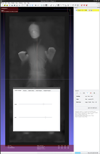
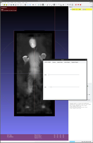
I screenshot both with the settings sliders so you could see how different I had to make it to get it to work

ortho view:

non ortho view:

6 Likes

It would be a public service if you reposted those settings to the Meshlab thread so I don’t have to keep two bookmarks stuck together. ; )

Yeah, I can get it sometimes, but not all the time.

Here’s an example:

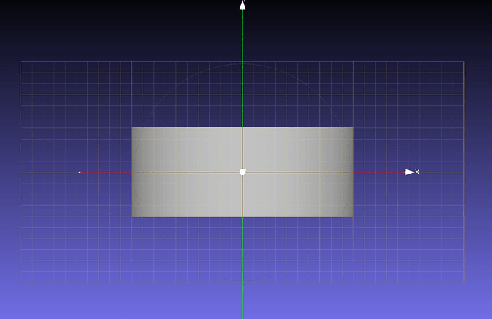
I made a cylinder in Blender with straight walls and one end open. All the walls have thickness (think, a cup with no handle).

Rendered in Blender, orthographic, depth:

Rendered in Meshlab, orthographic (from bottom), depth:

Great!

But, switch the view to the front…

Blender:

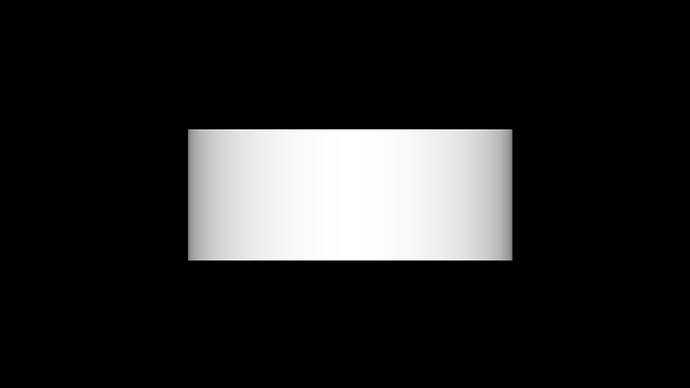
Meshlab:

The Blender render has gradients since the shape is round, where as the Meshlab render does not – it is solid white. No slider manipulation in Meshlab could get that to be gradient, and looking at the image in GIMP, it is only black and white, it’s not just a case of non-equalized gradient. :frowning:

It just makes it difficult to determine when things are right or not.

This all said, Blender isn’t the panacea one might think, or that I might appear to be making it out to be. Since this is depth based on distance from camera, you still have to adjust object positioning to get a good gradient range, even with a normalize pass in the render tree. (I did also adjust the positioning in Meshlab but that didn’t help).

I feel that there could be a specialized software tool made to do what we want without all of the variables needing to be tweaked… :wink:

2 Likes

A combination of different levels of zoom and slider positions is sometimes necessary to get it to display properly. Mind sharing that stl so I can try it?

You got it! :slight_smile:

depthpass.stl (12.6 KB)

I imagine there could be a specific set of things one could do to get any object within the correct depth range and shader setting range, which could almost be scripted (or at least written down). I might have to play later after work.

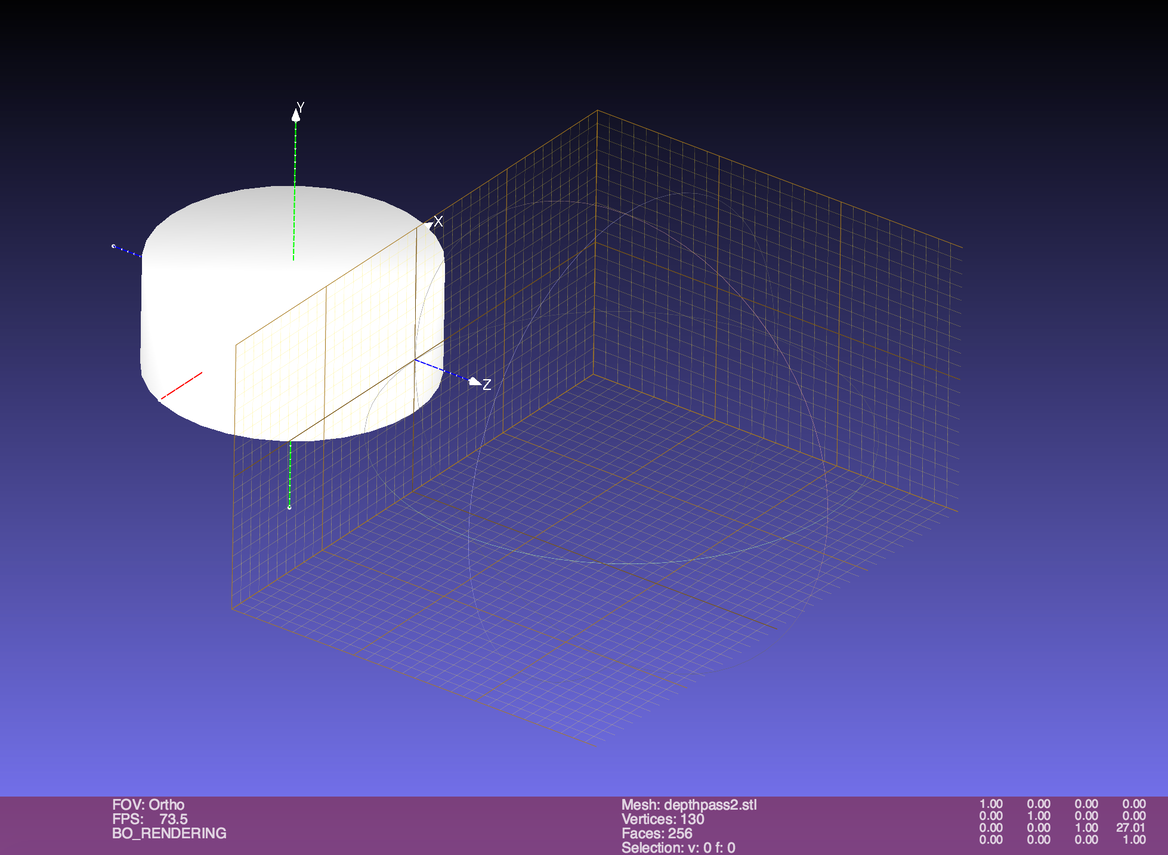
Spending a little bit of time over lunch on this, if I translate this object to the back-edge of Meshlab’s grid cube, then look at the front view with the depth shader, it works. :wink: :man_shrugging:

ML_ortho_transform

The same thing didn’t work for a different object, but I could get it to fall within some bounds where the sliders work by translating it in space.

I totally agree with your assessment that some combination of zoom and sliders is what’s needed, and add – sometimes – a translation in space. Just how to make it consistent…

1 Like

Im very tempted to rewrite the shader to always set the visible max bounds based on objects in the scene. I havent written a shader since quake 3 came out though lol

Scaling the object to fit the area should help as well…

2 Likes