I could have sworn I did ortho with meshlab, you just had to fiddle with the ranges. Ill have to double check, been a while since I messed with it. Good lookin out =)
I’m not sure if anyone else has tried this on a Mac, but it did not work for me.
1 Like
I have a mac and a PC. I dont remember which one I did it on. Probably PC. Thanks for the info =)
When I have more time, I will try to provide a little more detail than “it did not work.” All I can tell is that meshlab seems to have some differences on the two platforms.
Don’t have a functioning phone at the moment to post my print, but I used this .stl:
https://www.thingiverse.com/thing:132189
to get this:

using your tutorial on my Linux machine just before Halloween and was pretty happy with it. Thanks, @takitus!
10 Likes
Trying again this morning, it appears as I can get ortho in Meshlab to give me a grayscale depth map but only with specific view angles, which change depending on object (sometimes bottom, sometimes front). For most of my tests, any other view or angle goes all white or black, regardless of slider settings. 
Humorously, there is only one other post online about depthmap shaders in Meshlab not working correctly, and it’s from 2014 from a user who wanted to do exactly what we’re all talking about 
In @scatterbrains’s Hufflepuff crest image, I see it is doing the perspective warping. The shield at the top doesn’t appear centered, and there’s a “shadow” on the ribbon to the right. It’s most noticeable in the flourish of the “H” where there’s a gradient to black:

Compared to the same section from an orthographic depthmap I rendered from Blender (with black background):

The “H” flourish and ribbon don’t have gradient depth, and the shield at the top is centered.

Again, there’s nothing inherently wrong with the perspective view, it’s just not 100% accurate to the object being used. I think if you were trying to align something engraved using this method to something either 3D printed or cut in a different way, there could be issues. But if it works, it works! 
3 Likes
I was able to get it working in ortho just fine, it just took a bit of fiddling.
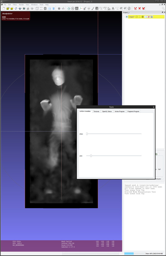
I screenshot both with the settings sliders so you could see how different I had to make it to get it to work
ortho view:
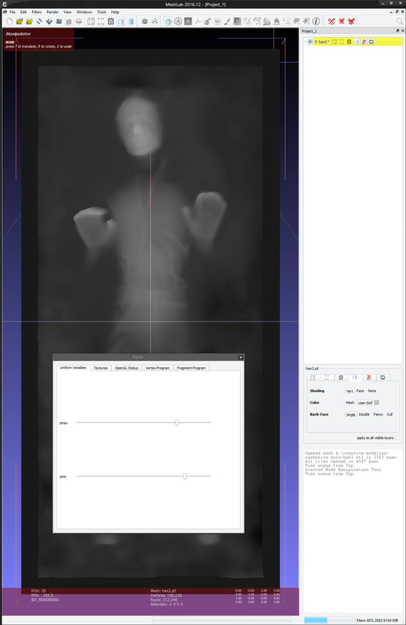
non ortho view:
6 Likes
It would be a public service if you reposted those settings to the Meshlab thread so I don’t have to keep two bookmarks stuck together. ; )
Yeah, I can get it sometimes, but not all the time.
Here’s an example:
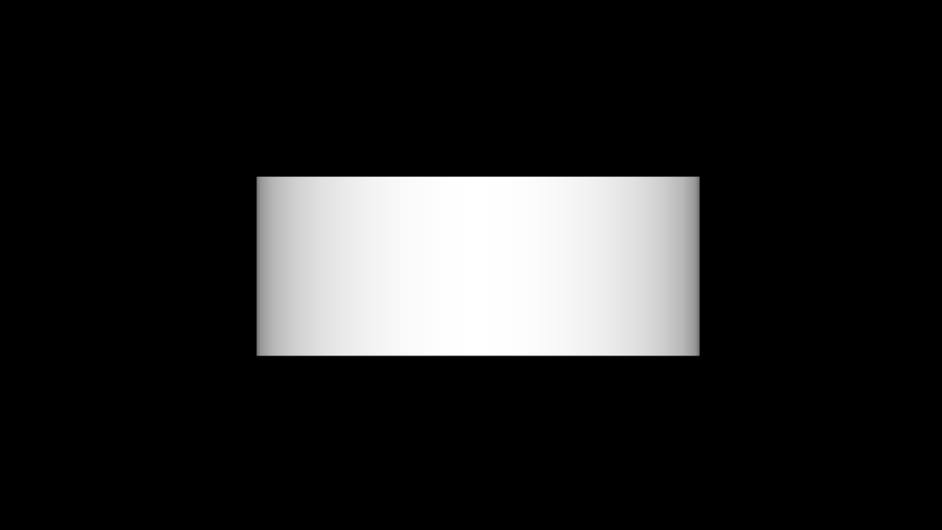
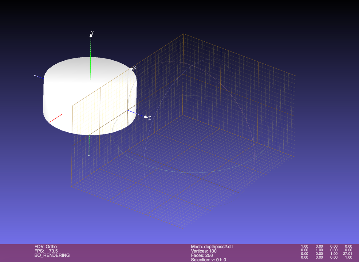
I made a cylinder in Blender with straight walls and one end open. All the walls have thickness (think, a cup with no handle).
Rendered in Blender, orthographic, depth:
Rendered in Meshlab, orthographic (from bottom), depth:

Great!
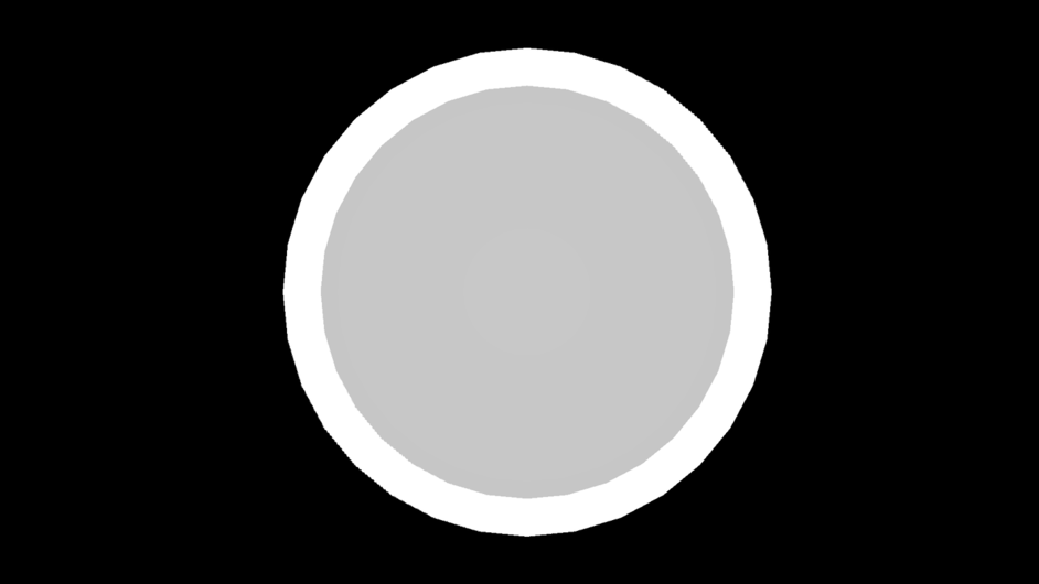
But, switch the view to the front…
Blender:
Meshlab:

The Blender render has gradients since the shape is round, where as the Meshlab render does not – it is solid white. No slider manipulation in Meshlab could get that to be gradient, and looking at the image in GIMP, it is only black and white, it’s not just a case of non-equalized gradient. ![]()
It just makes it difficult to determine when things are right or not.
This all said, Blender isn’t the panacea one might think, or that I might appear to be making it out to be. Since this is depth based on distance from camera, you still have to adjust object positioning to get a good gradient range, even with a normalize pass in the render tree. (I did also adjust the positioning in Meshlab but that didn’t help).
I feel that there could be a specialized software tool made to do what we want without all of the variables needing to be tweaked… ![]()
2 Likes
A combination of different levels of zoom and slider positions is sometimes necessary to get it to display properly. Mind sharing that stl so I can try it?
You got it!
depthpass.stl (12.6 KB)
I imagine there could be a specific set of things one could do to get any object within the correct depth range and shader setting range, which could almost be scripted (or at least written down). I might have to play later after work.
Spending a little bit of time over lunch on this, if I translate this object to the back-edge of Meshlab’s grid cube, then look at the front view with the depth shader, it works. ![]()
![]()
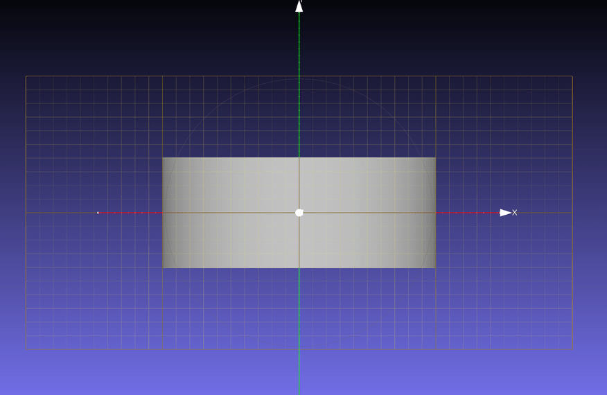
The same thing didn’t work for a different object, but I could get it to fall within some bounds where the sliders work by translating it in space.
I totally agree with your assessment that some combination of zoom and sliders is what’s needed, and add – sometimes – a translation in space. Just how to make it consistent…
1 Like
Im very tempted to rewrite the shader to always set the visible max bounds based on objects in the scene. I havent written a shader since quake 3 came out though lol
Scaling the object to fit the area should help as well…
2 Likes
The max and min settings are quite sensitive. I am working with nearly-flat objects, so the two settings are quite close. I’m not sure why they don’t default to the actual max and min depths of the object, and instead makes you scrub very slowly until you find the points where depth changes from white or black to grey. But I’ve managed it with a dozen objects, now.
The “cylinder all white” meant that the min depth was past the middle of the cylinder, so everything you could see was close than the minimum depth, and thus white which is the closest color, and when it’s all black that means that the max depth is closer than the front of the cylinder so everything is further away than max, and thus is black, which is the furthest color.
Yes, far from obvious.
I’m using Meshlab 2016.12 on a Mac running MacOS 10.12.6.
1 Like
Yeah, whoever programmed their depth mapping shader didn’t make it dynamic enough. If I have time I’ll go back and write one that adapts to the size of the object only, and give more options as to how the sliders work etc.
1 Like
In case it wasn’t posted already, you toggle between orthographic and perspective view in Meshlab using View/Toggle Orthographic View.
And I gave this a shot again today with success. I am not sure why I was having issues previously–of course I didn’t really document my process. But I was able to successfully create a depthmap with Meshlab on the Mac and cut a job that came out amazing. I just need to figure out how to clean it up and I’ll post a separate thread.
3 Likes
sweet! looking forward to seeing it! love me some 3d engraves!
1 Like
I think the key is definitely pushing the object back behind the plane. I think maybe if it’s in front of it, in orthographic view it’s considered negative depth, and the sliders just don’t let you get it into range. Maybe?
Just for reference:
- Turn on the Background Grid under Render.
- Left click and drag to get a side-ish view.
- Move the plane in front of the object: click the manipulator icon (three colored lines meeting at a point), type T for translate, X Y or Z for the axis you want, then click and drag the plane. Return to accept. Click on the manipulator again to get out of manipulator mode. Also turn off the background grid.
- Select a straight on view from, of all places, the Window menu, View From.
- Select Orthographic (“5” to toggle).
- Now, do the business with Render->Shaders.
- When you go to save the snapshot, you can specify a white background if you haven’t set the background gradient colors in Preferences.
If you manipulate the plane while in orthographic view from a side angle after you’ve got the sliders all set up, you can see that it looks fine as soon as it clears the plane, and bad in front of it.
2 Likes