To adjust for kerf or not to

Thank you all for participating once again in a kerf discussion. Sorry for the analogy, but perhaps it is appropriate here. It’s like getting your colonoscopy. You know you will have to do it some day, but you sure don’t want to have to deal with it.

So I spent some time last night understanding how Inkscape deals with offsets. Here is the Inkscape manual for editing paths. Scroll down to the end of the section for examples and how to. Begin by setting your Preferences for Steps for the arrow key nudges and the four different kinds of offsets that are available.


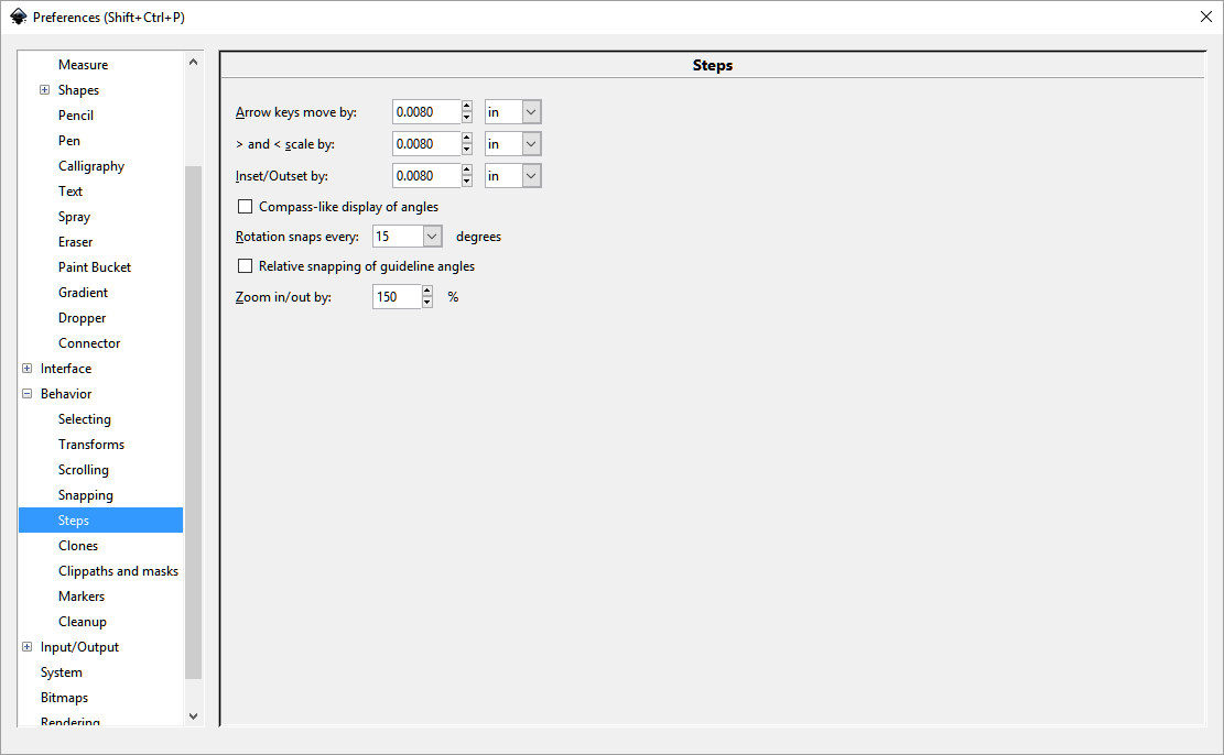
Ctrl+( is inset and Ctrl+) is outset.

I’ve had to understand how an object is measured. So if I make a 75 mm circle that puts a hole in an object, that is measured from the outside of of the line to the outside edge. Shrinking the line thickness shrinks the dimensions of the object.

From what I understand, Glowforge will use the center of the line for cutting. So if the kerf is 0.008" wide, I have to cut a replacement circle 0.004" outset to the original circle’s hole to fit in tight.

sorry for mixing up metrics here. I appreciate @smcgathyfay’s work and patience with this issue. I have a better understanding of how to proceed. It’s difficult to explain and comprehend without some real world experience here. Again, a test for abstract thinking.

22 Likes

My guess is that there will not be any kerf adjustment functionality in the GF software as dan has not jumped in on this thread or similar threads (that I could see). I have been thinking on how to deal with the kerf issue a lot as I have to create a very snug fit between the Alnico rod magnets and the top and bottom flatwork with holes for those magnets. I’ve decided to do the adjustment in the parametric modeling software (Fusion 360 in my case). I create a variable named something like “kerf_adjustment_magnet_hole” that will be a few thou’ in size and adjust the size of the hole for the magnet to create that snug fit.

Something like:
diameter_magnet_hole = .195"
kerf_adjustment_magnet_hole = -.015"

So the actual hole size is the formula:
= diameter_magnet_hole + kerf_adjustment_magnet_hole
= .180"

This way, adjusting for kerf in one aspect of the model doesn’t have to impact the effect of kerf/kerf adjustment in another part.

You can see in the image below how important the fit can be where it provides 100% of the structural integrity for the part on which a lot of force will be created when the wire is added to the pickup.

5 Likes

So what we are seeing is the jig you are using to drill the pickup scaffolding?

1 Like

The jig is to align for the pressing of the rod magnets into the bottom piece of flatwork and press the Alnico rod magnets into the top flatwork of the pickup. Below you can see the assembled bobbin in my 1 ton arbor press after the magnets have been pressed into the bottom flatwork piece and the top flatwork has been pressed over the top of the rod magnets. The brass pins align the top press that you can see sitting on the base just behind the bobbin in the press jig. I want to use the Glowforge to cut the top and bottom flatwork from the forbon flat stock. I have used my Shapeoko 3, but it’s just not the right tool for this job.

I built this jig and others on my Grizzly G0619 milling machine.

5 Likes

I’ve mentioned this before - for Proofgrade materials, we’ll automatically compensate for kerf.

13 Likes

@dan, will there be manual setup kerf adjustment for non proof grade materials? I’m confident that there will be some of out there that will primarily be using other than proof grade materials (e.g. In my case, I will be using forbon most of the time).

3 Likes

For both 3d printing and laser I have started out with a sample piece with a bunch of holes or pegs at 0.1 mm intervals as a calibration piece and then apply the correction to the outline when accuracy is needed ( gears).
Most cad programs have an offset capability to do this easily.

1 Like

In the hopper, but you can always do an outline stroke or similar to accomplish it in the mean time.

5 Likes

I cannot give enough likes to this!! Insta-kerf compensation? Yes, please!! Thanks!!

8 Likes

Will we be able to disable this even for Proofgrade materials?
Sometimes I need to be able to adjust part of a cut but not the whole thing.

8 Likes

@ dan

WOW. . . You’ve got to be kidding me. I get kerf adjustment right away if I buy your Proof Grade materials, but if I want to use my own materials I don’t get kerf adjustment or at least not until whenever.

If it is available for Proof Grade then it would have to be part of the current software functionality, have to be part of the file sent to the cloud and consequently only a button and input box away in the interface from being available for non-Proof Grade materials. Am I missing something here? I mean, you’re feeding the CAM equivalent file with a positive kerf adjustment value for Proof Grade material cuts and ensuring it is “zero” for non-Proof Grade cuts.

So if I understand correctly. . .

Cut parameters for Proof Grade materials are:

Speed/Power/kerf adjustment

Cut parameters for non-Proof Grade materials are:

Speed/Power

WOW. . .

To me, every time I hear the expression “in the hopper”, given the thousands of things in there by now, I equate it to being in Never Never Land. Obviously I can make adjustment, but I don’t want to be forced to when the functionality is built in for OEM materials.

There. . . I didn’t swear, I didn’t insult, I just got something that is important to me off my chest. And ya, I know, some are still going to beat me up about this post, but I guess that’s life.

9 Likes

Might be wrong, but I believe the reason that they will have kerf adjustment for proofgrade materials, and not any-other-thing-we-might-throw-in-there, is because they will have more control over the nominal sizes of the proofgrade stuff, so they can hardcode those values in, giving beginners an easy way to get started.

(In other words, we won’t even have to see it, it will be part of the code associated with that material, accessed when the scanner reads the bar code.)

And there might not be much in the way of acceptable proofgrade stuff at first as a result.

Lot of variances in material thicknesses out there. From reading up a bit on stuff found in the forum, my understanding is that kerf can change a significant amount depending on the thickness of the material. Certainly enough to impact the fit on those pegs.

But since you have apparently already created your design in Fusion 360, and accounted for the kerf with a parametric variable, why would you need an additional kerf adjustment? It’s already built into your file?

Anyway, I’m just guessing, so don’t hold me to it.

4 Likes

I am fully aware that my non-Proof Grade materials will require me to “tweak” the kerf adjsutment to get them down, but once “tweaked” that’s it, my .093" or .060" Forbon manufactured by my same supplier will always come out the same with the same kerf adjustment. I would not need to “tweak” different parts of a part for different sizing relative to my CAD drawing. I want my cut to be my CAD drawing exactly as it was designed without having to mess with it in the CAD to compensate for the cut at the laser software. This is absolutely the same as defining the bit size for a CAM setup for my CNC router. The bit size tells the machine how far to stay away from the line. It is a variable in every CAM program on the planet for every CNC router on the planet. This is a big deal for those bringing their designs off a CAD system where they have been using them on a CNC machine. A very big deal. As I was saying in my post, if they are adjusting for kerf in Proof Grade, they absolutely have a variable in place to be used by their in house CAM software.

6 Likes

So you’re implying that I should be required to create 2 versions of models (drawings), one for Proof Grade materials where the kerf will be compensated for and a second for non-Proof Grade materials where it will not be compensated for. If I cut my model on a Proof Grade material I will get exactly what I created in CAD and wanted as a part, but if I use non-Proof Grade material you suggest it is good to force me to jump through hoops to get the part the way it was designed. Really? You honestly believe it is better for Glowforge not to provide the ability to do kerf adjustment for non-Proof Grade materials?

3 Likes

I think that Glowforge is going to eventually provide a place where we can create kerf adjustments for whatever material we have to use.

But I don’t know that that functionality is going to be available out of the gate.

Further, if you are using the parametric design correctly in Fusion 360, you only have to create the file once, and then you can either use a kerf adjustment or not, by changing one number, once. Which is exactly the same thing that you will have to do if Glowforge creates an adjustment slot for us to use in their software. So it’s easy enough to create the parametric model, just save a copy of it with zero in the kerf-adjustment slot, and then use it when you buy proofgrade. Not a whole lot of additional work.

What I am saying, not implying, is that several people, yourself included, might be confusing parts of the design process with what the laser file creation software is going to provide for us at first. It’s not going to be able to perform all of the bells and whistles up front. They might add some of those functions later, but my understanding was, that if it is available in other freely available software (eg: Fusion 360, 123D Make, Inkscape, etc.) they are not going to try to re-invent the wheel for the crowdfunding release.

The only things I’m sure they will be including immediately will be an auto-trace function, variable depth engraving, an automatic adjustment for material thickness with correct focus so that the laser always cuts through the material that we plop down, and the need for no kerf adjustments on their proofgrade material.

And that’s actually quite a lot.

If we want to do vector design, the rest is on us.

Think about it and decide if it’s still what you want. It’s going to be a while before we see some of the goodies, and that might be a deal-breaker for you.

7 Likes

I don’t know why, on this issue, you have decided not to support Dan and his direction on kerf adjustment. Dan is right, kerf adjustment is a requirement and he has seen that it is part of the functionality of the Glowforge. Why are you not on board with this? Why do you keep driving and driving as to why kerf adjustment is not important?

1 Like

I didn’t say it wasn’t important. i said it might not be available. (initially)

Its not that its NOT important but you need to understand that all kerf adjustments are not the same…there are many different applications for using kerf adjustments. If it automatically did kerf around all lines then you will have too much in the parts that are butted up next to each other…and in the case of slots, you dont want kerf adjustment on both the inside and outside…then it would be double and leave too much gap. Sometimes you want the pieces to fit snug together, sometimes you want them to slide out.
This needs to be done in the designing…

7 Likes

With all respect, not everyone does those type of parts. There are those like myself that make parts that are required to be precise to the CAD creation in all dimensions.

2 Likes

I’ve got an idea. You’ve obviously got a special circumstance here that the GF as currently designed isn’t going to handle to your satisfaction.

I think there are a few Fusion 360 experts hanging around.

Why don’t you post one of your Fusion 360 designs up and ask if someone on the forum would be willing to help you get the kerf issue squared away in your file? Once you determine what the actual kerf is, you’d just drop the number in place and off you go. It’s going to stay the same every time you use the same material, Fobon, proofgrade, or whatever. When you use a different material, you put a different kerf number in, and the file adjusts itself for that.

I’ve done it a couple of times - I’m definitely not an expert yet - but the program does all the heavy lifting, and it’s amazing to watch.

Take advantage of the expertise on the forum while we’re waiting. :wink:

3 Likes