As was I and it was probably the largest major factor in my purchase. It’s nothing more then a tool/bit size variable. I don’t want to over size my drawings or add a extra outline. With any cnc deaign what you put in cad cam is what you get you tell can this is my bit and it figures out tool path to make the out put as designed you don’t go into your design and change a value to make the part different sizes
9 Likes
Another +1 for manual kerf adjustment in the GF interface on non-proofgrade materials. While I agree that it is not hard to make adjustments in the CADD world and I have been designing my files with this in mind. I also think that every step to making the GF easier to use than everything else out there is a step in the right direction.
7 Likes
While it may not be hard to make certain types of adjustments in the design file, it is dead nuts simple to make it in the CAM app (e.g. Glowforge software). And to boot, it gets made one time in the app and every user that would make use of it would never have to make a kerf adjustment to a CAD file ever again.
This is an example of how easy it is, and this by a bumbling old retired CA (CPA).
Here is a screen shot of the CNC guitar pickup winder application I wrote.
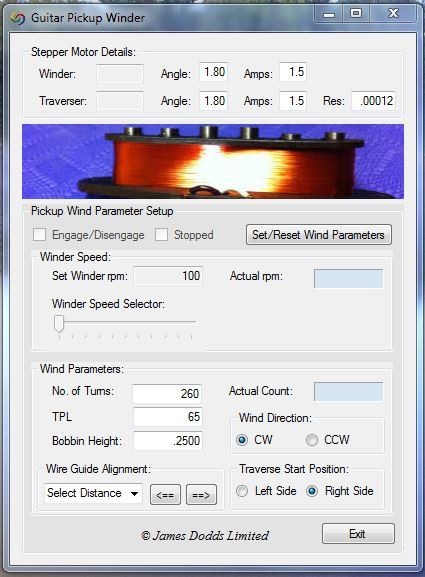
You can see the area in the bottom left corner entitled “Wire Guide Alignment:” That is the kerf adjustment for my CNC winder app. It aligns the wire guide with the edge of the bobbin, just like adjusting the laser cut for the line edge of a drawing.
Here is a screen shot of the code attached to that section:
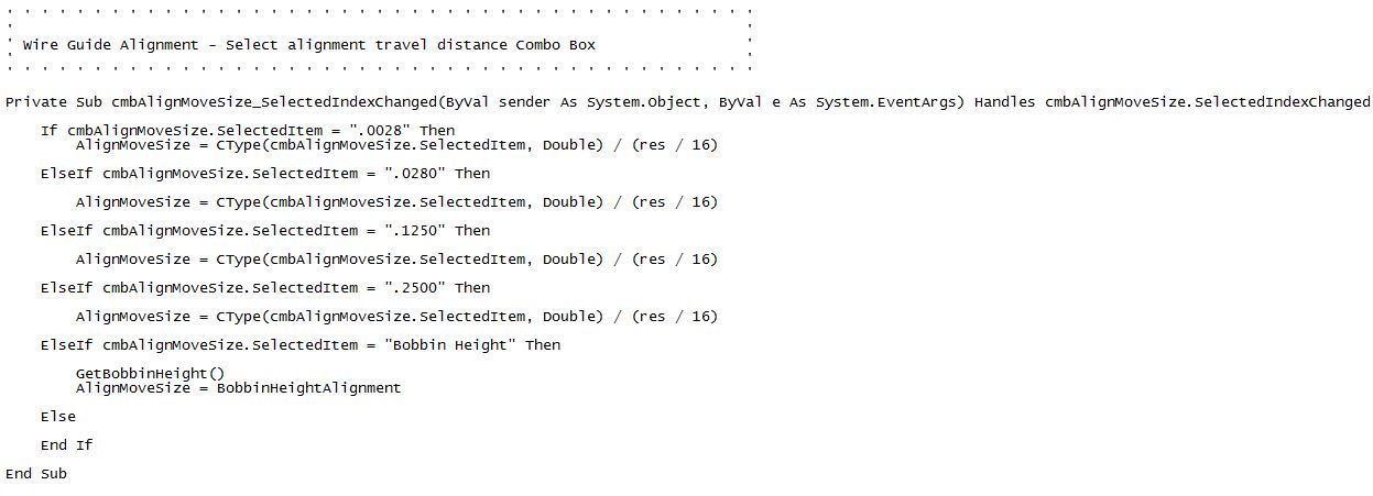
I know it’s not the Glowforge CAM app, but what is it? 20 lines of code? How long did it take me to create the code and the related interface and test it? Under 2 hours. But Glowforge has already done this, they are just grabbing the kerf adjustment from a data file vs. screen input. So how long would it take coding professionals to create the screen input? 15 minutes? An hour? A day?
Again, I really don’t get the “in the hopper” comment on this one. Something so fundamental to the product, something so simple to incorporate, something that is already incorporated for another aspect of the product (Proof Grade materials). Something that should be in the Glowforge right out of the gate.
8 Likes
Thank you. 
4 Likes
Wow!!! as usual the amount you bring to the community amazes me. thank you.
3 Likes
I suspect some folks might be making some assumptions here.
In reality, we all are making a lot of assumptions because we haven’t actually seen the Glowforge work, so we can’t know how it will actually work.
The dreamers who thought this thing up were a group of three to maybe a dozen people. Their customer base is now in the thousands and a thousand people can think of more use cases than a dozen. Just because they haven’t already got a demo to prove how a function will work DOES NOT MEAN that they are not going to address it. I’m going to assume that they will.
I suspect many people will need to adjust the files that they are creating now. The first cut on the GlowForge may not produce a perfect shelf-ready sellable object.
Proofgrade may ultimately not be a device to frustrate everybody who doesn’t buy it. It just might be the easy and simple stuff for the risk-averse customer who doesn’t want to deal with figuring out their own materials.
The guys who are willing to spend some time in trial and error can probably dial in their settings so the Glowforge will work for them just as well as it will for the proofgrade user. Maybe not - but I’m going to make the assumption that they will have every bit as much as a delightful experience.
I’m delighted that they are working to make the machine work predictably with proofgrade materials… I suspect that those efforts will translate to better and more predictable results with materials sourced elsewhere, too. How Impressive!
@smcgathyfay - what a great tutorial! Thanks very much.
8 Likes
I decided to make a screen recording that will explain kerf and kerf-compensation. It’s about 15 minutes long, and I use the phrase “drive it home” far too many times, but I think it will clear up any lingering confusion.
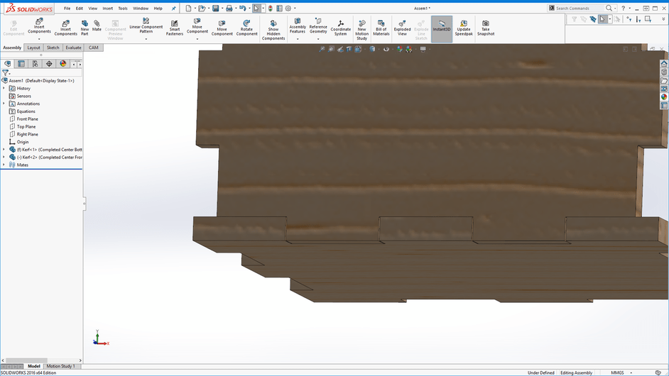
And here’s the file I used. It’s a SolidWorks 2016 file, so many programs probably aren’t going to be able to open it.
Kerf.zip (961.6 KB)
24 Likes
Nicely done! 
5 Likes
A lot of the arguments here make a ton of sense, and there’s clearly a lot of passion around them. In my view that puts this hopper item a lot higher up in the priority list that a lot of the other things that have been thrown in the hopper over these months. That would be especially true if it turns out that it really is that easy to add it, which it should certainly be; I’m guessing the biggest obstacle will be the design challenge of making that field available for those who need it without confusing the people who don’t.
6 Likes
Thanks for that video Hirudin!
2 Likes
Excellent video! 
(You should post that in a separate thread so we can tag it with Tutorial for later, like @smcgathyfay did with hers .)
One thing you didn’t show, (that i would like to see), is the gap caused by the center line cut at 0.2 mm (which is what the machine is going to do).
Great job putting that together.
4 Likes
Can you even imagine adjusting all your Fusion 360 (Solid Works) models for a tool diameter then entering a tool diameter value of ZERO in the CAM software. What a totally insane thought.
5 Likes
Having to adjust the part dimensions for kerf in the CAD model also means that you can’t properly check for fit in assemblies. Most of what I plan to laser cut will be assemblies of parts that need to fit together pretty precisely so it looks to me like user-settable kerf settings are a priority feature for that sort of use.
I hope @dan comments on this soon.
6 Likes
I’d just like to hear that manual kerf adjustment will be released into the product for non-Proof Grade materials at the same time as it is for Proof Grade materials.
5 Likes
Indeed if I have fake size all my assemblies and joint to compensate for kerf that is no way no machine shop ever operated. The nice the about cad is to see part integration’s and motions and conflicts. Fake sizing everything defeats cad totally for anything that needs to touch. I should put my file in at exactly the size I want the part and tell gf this side keep this aide scrap this is the kerf. And be done. I should have to under or over compensate for anything with bogus designs. This is a nerd rage thing that is a non starter for me and worthy of a order cancel So Yes I hope @dan comments soon
4 Likes
I’ve not heard of the term fake sizing before. But you have helped clarify expectations for me. So we make a design and say: this part is 4 inches by 4 inches. Actual dimension in the design. Send it to the Glowforge without any other manipulation. After it is cut, it measures exactly 4" x 4".
From what I read about designing with kerf in mind from folks who have lasers, that they must design to account for kerf. So the file sent to the laser will never be the exact dimensions of the finished part. And much of this discussion depends upon what design program you are using.
5 Likes
Thanks! ![]()
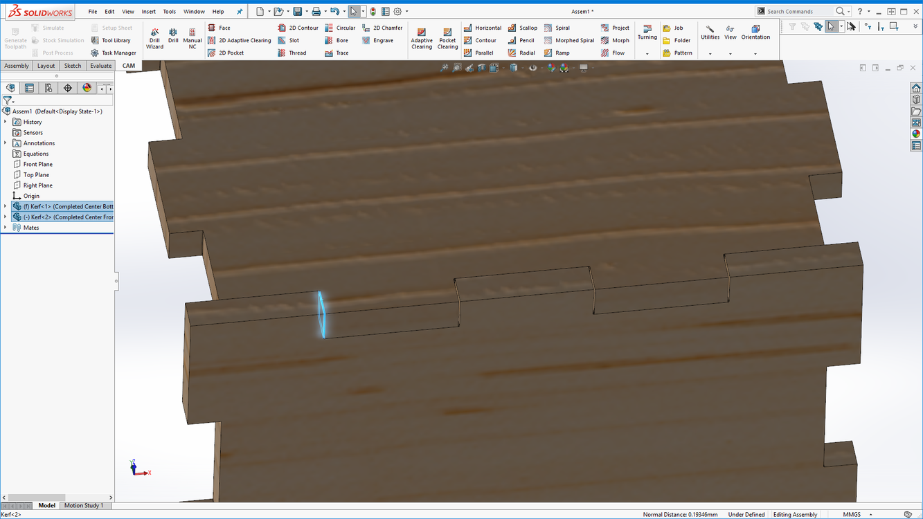
Yeah, I should have shown this in the video. Would a couple screenshots suffice?
I realized that the width of the gap created by two center-line cuts will equal “1 kerf”. So, the gap on each side of the tab is 0.2mm (~0.008") in this example.
Heheh! Yeah, that’d be productive!
6 Likes
Yeah that’s good! ![]()
3 Likes
I’m a hobbiest when it comes to wood, but I always knew to take into account the material the saw took out of the material. I am not sure why it’s surprising the laser would and why it is assumed it will be so hard to do it when the laser arrives. Having never used one I can’t speak from experience but I just don’t see why figuring in loss of material is such a big deal for the end user to do.
5 Likes
Was a good video, I am the one who gave it a like ;D
Between the video and @smcgathyfay visual aid, I finally understand kerf. Thanks gang 
3 Likes