Of course. I fully understand that different factors go into running these different machines. As you mentioned above, we are all from different backgrounds and different experience levels, so forgive me not being fluent in the history of computer-controlled machining equipment. I have zero history with either CNC or lasers.
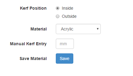
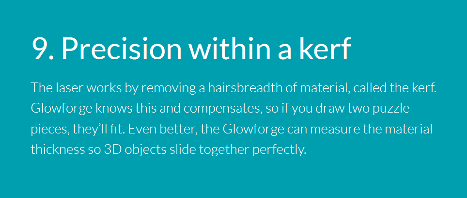
Given that kerf is discussed quite a lot, that various pieces of software account for it (box making sites for example), that it has sparked quite the discussion in this thread, and that it was advertised in the marketing materials (without reference to proofgrade materials), it is surprising that there is no manual adjustment for it.
Given that kerf is adjusted for automatically in PG materials, and that there is no UI to adjust kerf manually, I have a few follow-up questions:
Does the GF software automatically add this kerf variable to all cuts made on proofgrade materials?
Is there a way to disable this for proofgrade materials (in the instance that you have already accounted for it in your design).
If you don’t use PG materials, is this value just set to zero? Or is there some nominal kerf value that is added regardless?
ya agree with you this was a MAJOR selling point to me in there bullet points of selling points. being able to set a tool size basically and not have to fake size designs with a sacrificial buffer for ablation. I am disappointed thus far its only confirmed to work with proof grade that means the functionality is there just no exposed way for us to do it. interesting point when you program something you have to have a exposed way to tinker with the settings. so how did they program all the proof grade stuff… by hard coding it every time and doing a run I think now. I think they modified either a setting that we are asking for be exposed or a table some place that the motion planner references when it does it work up
there should not be a debate if or why we should be able to enter what is the equivalent of tool size. its ultra basic functionality that I remember being part of any CNC work I did 20 years ago in school and that my brother still does today. makes a design true to intended purpose, loads the file in to his monster of a machine and tells this line this head this line that head etc… no fake sized designs
no its not. if you design it 4x4 it is going to 4x4 because in the cam profile you told it tool size be it a 1inch bit or a 1/32 inch bit
in no case what so ever do you over size your designs because then none of your motion analysis will work or your contact / interfaces and then if you get complicated you will also mess up your structural analysis. you always design for what the part is meant to be and what the size of the tool you are using is and the motion plan takes this to account and puts tool to the edge of the design indented vector and runs the part at exactly what the design was designed out with out added buffer
like I said in a previous post this topic has me on nerd rage so if anyone’s offended sorry
I have done lots and lots of CAD work and run quite a few various CNC processes and for those purposes I think you are (and @jdodds and @palmercr and @MikeH) are absolutely correct!
Now imagine just for a minute that there might be an entire group of people for whom this is all useless. For instance they are just interested in cutting signs out and thousandths accuracy is immaterial, Or they are going to be drawing on material with a damn sharpie and cutting it out, or they are just going to be doing engraving, or they are cutting out leather parts where the material is so flexible and plastic that a .008 kerf is something they can completely ignore, or they are making jigsaw puzzles and need the kerf so the puzzle works.
The Glowforge software has to be designed for ALL of those use case, PLUS the ones you care about. No one should take second seat, that just is not fair. Plus the Glowforge company, its investors, and its employees need to make money.
Obviously there will be compromises made, and we just have to hope that the folks making them make the right ones. (I am glad it 'aint me!)
hey I’m all for auto whatchamajigs but I still think there needs to be some type of tab or check box to enable manual entry for speed power tool size (kerf via observation of test runs and measurements etc…) we wont all be using proof grade as most of us (we don’t yet know the cost) but if its reflective of some of the other laser source material sites we can find it cheaper in bulk for things etc… so I am disappointed kerf adjustment still even at this phase only works for PG with out manual input for non PG material. this was a HUGE selling point for me
I believe @Jules was reiterating the problem with ignoring kerf.
That quote could be rephrased to something like this “if you want an accurate cut you don’t want the 4 x 4 square in your design to be cut out at 3.9921 x 3.9921”.
the method proposed in the post still involves over sizing the design. You don’t do kerf adjustments in the design you do it at the tool interpretation layer. You don’t want to have to keep re opening a design every time you have a kerf adjustment to make its mich simpler to pull the design from file that you have used 100 times and is known good and then at the tool tell it the tool size adjustment and say cut left of line or right of line or Center. Plus with any cad designs having oversized parts to compensate what the tool will be doing will mess up part motions and joints so it’s just not an acceptable work flow for anything that’s going to touch.
But really we are all spinning our wheels here as we have already been told machine level kerf adjustments at this time only work for proof grade. So until that changes we have to assume that everyone else not useing PG will have to fake size there parts for our own matts and true size parts for PG
As far as I know, up to now…kerf adjustment has always been done in the software for lasers. The Glowforge is “forging” a new path utilizing onboard software to do much more than traditional lasers.
There are some with cameras that can recognize registration marks but thats about it.
Are there any Glowforge-generated kerf compensation detractors out there who actually have proficiency with CAM software?
The “I don’t trust computers” sentiment is strangely ironic when we’re talking about a cloud-driven CNC laser cutter with alignment cameras and autofocus. You’re trusting it to adjust the laser to the power level you want (no small feat by the sound of it). You trust it to pulse the steppers at the speed that you want. You trust it to convert your geometry into cut-paths. You trust that the data will be uploaded and downloaded without error. You trust it to convert your filled vectors and raster images into engrave paths. You trust it to automatically turn on the air assist and exhaust fans.
Performing an offset. THAT is the thing that you don’t trust?
Also, this sentiment is coming from people who are advocating that THE EXACT SAME THING should be done, manually, using OTHER SOFTWARE!
I’m actually talking about a method to parametrically set up your design that essentially duplicates what you are asking for with an offset from glowforge. It takes a minute or two to set up, but once you do, it’s as easy to use as changing one number. and it is non-destructive to your original file.
Tomorrow you can look at it and decide for yourselves if you can live with it until glowforge creates something.
It’s meant to be a temporary work around, not a way of life.
Okee-dokey?
Going 2 sleep now.
(man you can so tell when I’m trying to type on an ipad in the dark!) ROFL!
One reason this is a big issue is that with most CNC machines you have a separate CAM program that does the kerf offset and produces gcode of the adjusted toolpath that goes to the machine. That means you can use what ever CAM program you want. Glowforge with its cloud approach has taken over the CAM stage and doesn’t accept a gcode tool path. So it needs to be able to do everything you can do with other CAM tools or it makes the machine less capable / flexible than a conventional laser cutter. Either that or it should accept a gcode toolpath.
Hold on there. Glowforge accepts SVG. Are there CAM tools that accept DXF or SVG and can output same? (All those fancy toolpath simulations have to come in some format.) If not, coding one up should be a fairly simple matter – SVG is complicated, but the parts of it that GF is going to use really aren’t. Or a gcode-to-SVG filter (once again, for the parts that are meaningful for a laser cutter). The longest part of the programming would be finding the right winding code to steal.
Oh, wait. Inkscape is scriptable. So are we talking about anything more than code to figure out which loops are exterior and which are interior and doing kerf/2 outsets and insets before saving as lase.svg?
Most CAM tools output gcode to send to CNC machines. They don’t output the tool path in any other format because it has feed speed, etc, added to it.
Yes I can write my own tool offset code, I did so when I made my first milling machine / 3D printer, but why should I when I spent thousands of $ on a Glowforge from a site that boasts it as one of its 12 revolutionary superpowers?
How did I miss Kerfgate yesterday? Here I am thinking nobody is posting anything good to read. I kept skipping over this thread thinking it would be boring… How wrong was I? Thanks for all the entertainment, and yes between it all some really good information about kerfs.
Oddly enough, there is (at least) one CAM package that will not only output an SVG, it’s apparently specifically.intended to be used with a Glowforge. Here’s the first post that I know of that talks about it…
And here’s a thread that @Clone started to talk about it further…
I’ve tried it in both Fusion 360 and HSMWorks and it works pretty well. It’s not perfect, but it’s OK. @Jules. I know you’re working on a tutorial to show how to offset sketches in Fusion 360 by a parametric value, maybe I could supplement that by recording a video about how to use the Glowforge post processor in HSMWorks (or maybe even in Fusion 360, though that video has already been made once).
Why do I say it’s just “OK”? Well, the SVG it generates is less a collection of shapes and more a collection of lines. Each line segment is its own entity. The laser cutter that I happen to have doesn’t seem to have a problem cutting with a mishmash of hundreds of individual line segments. This laser, perhaps by virtue of using a printer driver (a form of CAM, to keep the nomenclature consistent with the rest of this thread), seems to automatically join the lines together.
So, what’s the problem? Unlike my printer-CAMed laser cutter, Glowforge has had issues with unjoined mishmashes of lines. Here’s a post from @dan stating this…
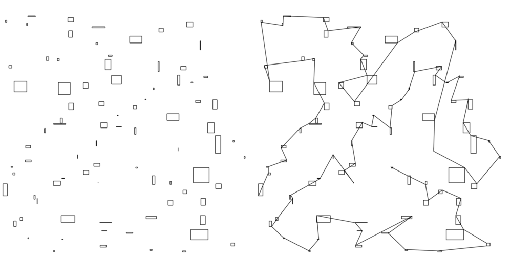
OK, fine, the lines aren’t joined. No big deal, right? Sorry, that is a big deal. As best as I can tell, joining the lines in Inkscape means selecting two joined lines individually, then selecting the point at which they are joined, and then executing the “join” command. A process that would literally take hours with some designs. Illustrator is a little better, at least you can select all the unjoined lines at once, but it has a strange proclivity of also ADDING a bunch of unwanted lines in the process. Here’s a “before and after” image I created and posted in the above thread to illustrate the mess this creates… https://community.glowforge.com/uploads/short-url/zUHGpvI63KTRsI0WIPrtFuZUCAN.png
This is better than Inkscape, but not by much. I don’t have Corral Draw (or even know that it’s actually “CorelDraw” ), so I haven’t tried joining the lines created by the Glowforge post processor in that yet.
Rhino will join these lines perfectly. OK, cool, so it must be that I just like complaining, right? Although that might be the case, Rhino has one fatal flaw in this regard: it doesn’t open or save SVGs. At least, the version I have (v4) doesn’t, I can say that for sure. It’s possible it’s been added to the newest version (v5) but my quick internet searches seem to suggest that opening this format is still missing from Rhino’s amazing file-compatibility list.
OK, so can’t I just open the SVG in Inkscape, save it as a DXF (I’m assuming Inkscape will do this), then open the DXF in Rhino, join the lines, save the DXF, then open the DXF in the Glowforge software? I think that will be possible BUT, here’s a somewhat recent post from @dan on that subject…
SO, currently the workflow would be HSMWorks post processor → SVG → Inkscape → DXF → Rhino → DXF → Inkscape → SVG → Glowforge.
Call me crazy, but I’m not the biggest fan of being promised things and then find out that those promises have strings attached (it currently sounds like you have to buy Proofgrade material to have the promise fulfilled).
And yes, I know the workflow can also be Fusion 360 → parametrically offset sketch → DXF → Inkscape → SVG → Glowforge. As I mentioned earlier (post 43) this workflow (while completely possible) is riddled with issues when dealing with parts and assemblies that are more complicated than a few 2D extruded sketches.
My current workflow for my primitive laser is SolidWorks → DXF → Rhino → offset → Trotec thing.
Im a bit late to the party here, but I would have to say manual kerf adjustment would be INCREDIBLY helpful. I cant stress this enough.
There are many times where I am cutting multiple pieces out of different materials that will have different kerfs, and I really dont want to have to go back, re-edit the file for a different material, re-export it, and then cut. That would be a pretty big pain in my butt. Sometimes I have to work with very precise clearances, and having one piece stick out more than the rest would mean a lot of additional work or re-work.
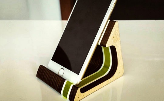
A simple example that I can show here would be the phone stand on the front page of the glowforge site:
Simple design, but 3 different materials. I wouldnt (who would?) want to have to sand the whole thing down afterwards because I couldnt adjust the kerf on the fly. I also wouldnt want to go back and re-export that file 3 times with different kerfs, much less try to design around a mechanical device that would use multiple materials. I currently have to do this with my chinese laser and it SUUUUCKS.
As someone who does a lot of multi-material work, its something that would go high on my list of features to have. I think it would be pretty easy to implement as well. (see below)


