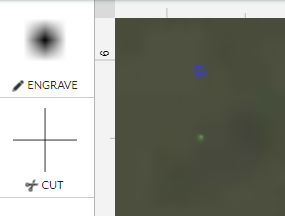
I have some strands of fiber optic acrylic and I want to etch away small dots of the shielding along the fiber. I want the laser to melt a round static point, not a line or a circle, just the smallest point that the laser can make. Is there a way to represent these points in artwork so they are placed where I want them? Like what is the threshold for a small enough circle that would get the laser to pause but not ignore the point?
You should be able to make just a single vector point for each dot, I would think.
Or a single pixel in a raster image at a DPI matching the engrave LPI?
You’d think so, but when I try that it says the file is empty.
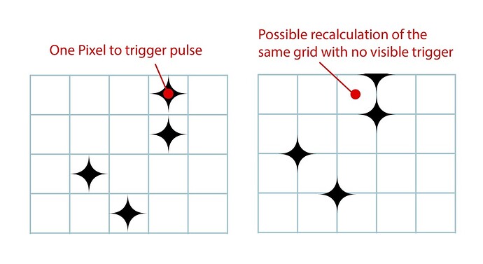
But how do I get my DPI to match the machines dpi placement so none of the dots fall in between the grid points? Its like a screen and if my screen isnt in the exact same place as the machines screen then the holes don’t line up. Is there a way to register such small placement?
Very tiny, two point lines seem to work, I will have to run some experiments to see what kind of control I can get
This is a pretty interesting edge case, it seems. Is this something you’ve tried and are trying to perfect or just trying to set it up to try?
It kind of goes against the general grain of things - since the laser has movement associated with it, rather than being a “drill” per se. So it will have a tendency to try and elongate in whatever direction the motion system is going. How noticeable that is, I can’t say. Plus, the beam probably isn’t perfectly round. I would say on another laser to just fire test pulses, but that also has problems since the duration would vary due to human error.
Yeah the speed and pulse are going set the limitaion, I figure I will have to deal with an oval instead of a circle. The process of nicking the fiber optic coating is pretty forgiving. I can get it to work with a small diamond burr on a rotary tool but I wanted to increase the resolution and get get better clarity with a quick melt vrs a grind. It’s a cool effect and I’m hoping I can push it much further with the laser. The nicks are visible depending on your angle of view and when you spin the fiber you can even get about 5 frames of rotary animation, kind of like a lenticular LED.
Cool project! Be sure to keep us updated.
If you fixed a light hardwood like basswood in a repeatable place ( I use 4" tiles in the front) and then score some straight lines at a specific number (say 6" exactly) if you then fit the fiber into the score will stay at the six inches when you put it back.
If you then typed ". . . . . . . . . . . " etc. and put that line of periods at exactly 6 " and making the power light it would put an even set of dots right down the fiber ![]() It might take some experimenting. @Jules wrote “Glowforge” on a grain of rice so she might have some pointers.
It might take some experimenting. @Jules wrote “Glowforge” on a grain of rice so she might have some pointers.
Make your art board 12" x 20" and the ![]() will override any DPI settings created by your art program
will override any DPI settings created by your art program
This is likely your answer, but if you desperately want vectors figure your kerf (the width of the laser beam) is around .007 so draw a + at .007. Here’s both for you to try:

Dots.zip (1.3 KB)
I think that is the heart of the problem with trying to represent the smallest usable unit with a dpi setting. Unless I can figure out exactly how GF will calculate the screen, I may be better off with vectors, as those are exact coordinates.
If I make a pixel grid based on a dpi calculation and have all of my pixels in the center of that grid, but glow forge starts it grid placement in the lower corner of the pixel instead of the center then all my pixels will be offset half a pixel outside of the visibility of the smallest unit. Or if glow forge starts the grid placement in the lower corner of the fist visible area instead of the art board itself I could get areas that don’t show up or moire. My final goal on this is to lay out the fibers in a jig that holds a fulls sheet and print a frame of animation across it. Its a needlessly complex mechanical screen that would work like a lenticular animation. Analog madness I know but I think it will look cool.
The coordinates don’t differ between a vector and a raster - if you place at 1x1 on a 12x20 board it will be in the exact same place whether raster or vector.
yes, but dpi is relative not a coordinate
Gf should implement dot mode where it makes a single static burn of a specified power and duration at every node in a path.
On the surface it seems like it would be pretty easy to do, yeah?
A dot mode would be cool, you could use it for drilling lots of very tiny holes.
Leveraging the rastser workflow for a precise coordinate matrix seems possible… but getting control of a single pixel placement in a moving system across multiple software packages with a variable resolution may be more than the algorithms were ever designed for. I imagine a burn dot averaging to the left instead of the right of a designated pixel grid is well within standard use tolerance.
Maybe.
I kind of feel like it would be simpler actually than existing motion systems, since you’re just setting coordinates, burn time, and burn power; rather than move between this point and this point at this speed but slow down this much before that point, and then speed up this much after that point, and modulate the power to this degree, etc.
But, how it would actually integrate with the existing expectations of the system… that’s where I think it would maybe not be so easy?
Maybe if you just put in a simple dwell time component?
That’s ui work. Glowforge is … uh… I guess I’ll let you decide how good they are at that.
Or if we could just send G-code… we can’t do that can we? Bypass the whole UI and go direct? Void the warranty big time:) no I just did a search for G-code and that’s not going to happen. Unless I use GF the unit for parts and get my own boards.
There was a whole movement to try to do this more or less called openglow. It proved to be a good bit harder than expected.
It’s much cheaper to go with a cheap Chinese laser Like a k40 if you really want to hack something together.
