When a print job starts, the GF positions the laser head about in the middle of the work area and a red laser shines on the surface of the material for a few seconds.
I’d think it’s measuring the distance to the surface for focus, except we tell the GF how thick the material is so it knows the focus already. And the camera doesn’t need it, we tell the GF the material thickness for that, too.
So what’s being measured and why?
3 Likes
It is measuring the thickness to set the focus for the laser during the job. Theoretically they could also do this to set the camera focus, but they face a few difficulties that they haven’t solved or coded up yet (it they have but haven’t yet released). One is they need to decide where to measure. After you’ve set up the job it chooses the geometric center of the design (ish). Before you’ve set it up, where? The other problem is when? Whenever you open the lid?
Anyhow, until they figure that bit out, we enter the material thickness manually so that it can use that value to do the camera image dewarp algorithm, that’s it.
5 Likes
The material thickness setting is used for two things: de-warping the lid camera image, and populating the focus height setting for any manual operations.
The red laser measurement is used to determine the focus height for Proofgrade operations, and any manual operation where you didn’t change the value that was filled in with the material thickness value.
The measurement also acts as a sanity check to make sure the material is within the allowable thickness range for lasering. For example, when you put something in that is too thick, or when the crumb is removed and the object is too far down…
Clear as mud?
6 Likes
I really wish we could do a ‘preview run’ of our cuts using the red dot. I bet that would eliminate a lot of the worry over optical alignment
The problem is that the red dot doesn’t hit that same spot as the real laser would.
It is fired at a 45 degree angle to allow for height measurement.
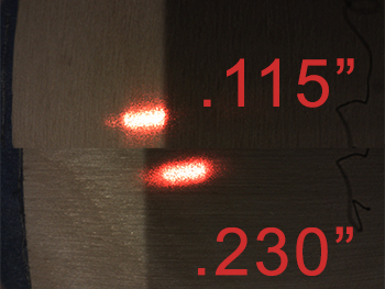
Here is the difference a little more than a tenth of an inch makes in the red dot placement (as seen from the head camera):
6 Likes
Yep, that totally wouldnt work then 
Thinking out loud…
The red dot seems to be intended to be centered under the head cam, which is offset from the actual laser. And, it has a known shift based on height.
If you took the measurement of the material first, you could calculated that shift, offset it by the camera-to-real-laser distance, and then run the program from there. The red dot laser would then track where the actual laser is supposed to fire.
There would be the caveat that it may not work near the edges of the of the laserable area, but that would be the only downside I can see.
3 Likes
Where I still don’t have my laser yet I have almost resigned myself to making the canvas size of my project the size of the laser bed so I always know where everything is placed
I still don’t get the concerns over alignment. Let’s ignore the economic argument against worrying too much, and assuming that there is an actual need to get extremely fine alignment (which there usually isn’t). It seems to me that any laser-based preview will take as long or longer than a jig setup, and is still more error prone than a jig.
What am I missing? Extreme cases where jigging is not possible? Maybe. I’ve not come across such a case yet but it could happen.
So if we agree that the laser won’t be faster or more accurate than a jig, what’s the appeal? Maybe some marginal improvement in convenience?
For me the dual cameras with “precise” alignment were the main draw to GF. I am familiar with pick and place machines that achieve precise alignment with cameras. This is why I haven’t accepted delivery of something with ±/1/4" alignment.
The fact that we’re dealing with warped materials, parallax issues, and fisheye lens corrections, it seems like a tall order to get anything approaching real-time precise alignment with the cameras… there are just so many variables. I don’t doubt that in an ideal situation it could be overcome, I just wonder two main things: Can the camera hardware precision we have now achieve that and is it worth the development cycles to chase it?
Add to that their server-based model that does the heavy lifting and now you’re on the hook for a detailed material scan (to account for warp) and upload to the server… all of which puts us firmly in the “I should have jigged” time category. I haven’t timed it, but my best recollection is that a proper jig workflow for a single item adds maybe 2-3 minutes to the job time (setup/breakdown of jig plus cut times in the 8-10 second range) and achieves conservatively 0.01" accuracy. I should time it next time I run a job, just to see.
What level of precision do you think is reasonable? I typically get to about a mm or two with my cameras ( I know there are people with much worse alignment), if I need more than that, it’s jig city. Maybe your tune will change once you have your machine, but I suspect its not as bad as you’re imagining it to be. I’m actually realizing now that I’m probably telling you a lot of stuff you don’t really need to know about yet since I don’t think you even have your GF yet… maybe we can pick this back up once you have your machine and can speak from experience?
1 Like
Camera pixel resolution should be possible. That coupled with Z measurement to 0.1mm should give alignment good enough for pass through and doubled side cuts. That is what was advertised. I won’t accept anything less.
I can easily make a machine myself that aligns with jigs. You can do that with a $400 K40.
To get camera pixel resolution, you need roughly camera pixel(ish) resolution on the material scan. That’s going to be prohibitively slow, I think.
I think you’re bound for disappointment. In any case, until you have a machine (or decide to cancel, which I guess is up to you), I don’t see much point in worrying about it. Go make your dream machine, it sounds like you’ve got the chops.
For a sheet material I think just measuring the height at the four corners of the bounding box would sufficient. Or the nearest point on the design’s perimeter to each corner of its bounding box.
Good idea, but I fear that theory doesn’t hold up to reality once you have your machine. I have seen complex bows and warps that would fail with that method.
I am sure the GF team has been working at this much longer than either of us, I think if there were a simple method they would have done it. Anyway, that’s my speculation quota for the day. Hopefully they’ll announce an update soon so you can take delivery of your machine… it really is a nice laser, the alignment is really good for the vast bulk of jobs… sorry your specific use case isn’t being met.
1 Like
Well the machine used to boast real time focusing, so it should be able to run the red laser around the perimeter of the object catching a height profile in real time. It doesn’t look like that will become a reality though now.
I’ve resigned myself to printing alignment marks before my actual print. Currently engraving a small (5x10") piece of PG leather, centered directly beneath the camera, but the corners that appeared to be perfectly aligned in the preview were each offset both vertically and horizontally by a pretty significant amount.