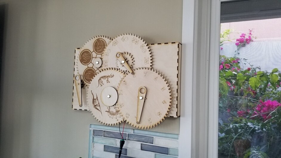
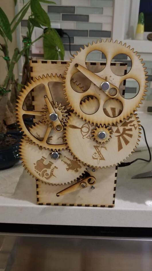
My buddy asked me to make him a simple gear for one of his projects. That led to me looking into the grear rendering function of inkscape, which in turn led to a few clock examples. So, one thing led to another and I found myself making this. The second hand is driven by a stepper motor running 3200 tiny steps a minute, driven by an arduino. Since that is not the most accurate source for a clock, I will be adding a reference timing circuit to the mix when the parts arrive. The glowforge part is done so enjoy. photos and videos

57 Likes
Most excellent! 
Wow! creative and impressive. Thanks for sharing it with us!
Very cool!
![]() That should be the warning posted above all of our doors.
That should be the warning posted above all of our doors.
7 Likes
@mark14 that is awesome. Can you share how you programmed the Arduino to control the stepper speed? I’m sure its all based on the gear configuration/size etc. Did you use a opensource code set, or program it yourself? Great work, and I’m sure it’s atomic clock accurate with 3200 steps.
It is a work in process. Right now, it is 3 lines of code that run within the main Adruino loop
if (micros() - lasttime >= 18750) {// seems fast by 6.25%.
lasttime = micros();
gooo(1, 0);
where “gooo(1,0)” calls a function that in this case steps 1 step in the direction 0 (vs direction 1)
here is that function:
void gooo(int far, boolean dir) {
if (dir)
digitalWrite(6, LOW);
else
digitalWrite(6, HIGH);
for (int b = 0; b < far; b++)
{
digitalWrite(7, HIGH); // sets the digital pin 7 on
delay(4); // waits for a bit
digitalWrite(7, LOW); // sets the digital pin 7 off
delay(2);
}
}
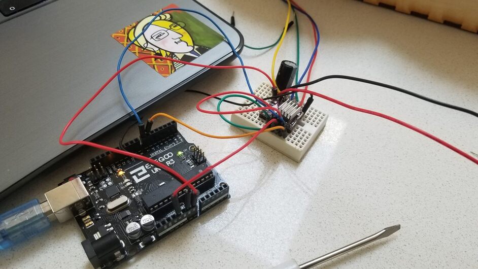
This allows the arduino to control a stepper motor control board via pins 6 (yellow wire = direction) and 7 ( blue wire = pulse high then low to step the motor 1 step).
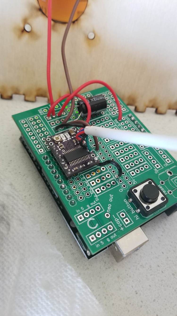
Stepper motors need motor controller boards. The motor control board is the little purple thing sitting on top of the proto board in the photo. These are low cost on amazon and elsewhere. As far as electronics go, not easy but not too hard. connections for logic power ( 5 v from the arduino) and motor power ( a 12 volt supply which the motor shares with the arduino) and 4 pins to connect the stepper motor and a few extra pins to configure it and enable it.
Since steppers draw power even when not moving, some of these pins make sense for other applications. Here, other than connecting a few of them to positive logic power in order to enable the board to drive the stepper, the only trick is I connected one of the pins to logic power in order to change the step size to 1/16th, which when applied to the 200 steps native to the motor, results in 3200 steps per revolution. very smooth. So, to make it go 3200 steps per minute, we need to move 3200 steps every 60 seconds, which works out one move every 0.01875 seconds. At least in theory. This is all rough wiring right now. Will clean it up with solder connections and no proto board once it is all working.
Adruinos unaided are not the best sources for accurate time keeping. This one is running fast by about 6%. So the next step is to add an accurate Real Time Clock (RTC) to the works. Here is an example of one
These are also cheap and once set, drift by very little (+/- 2 ppm). So, I will add this board (4 more wires) and then every 15 seconds, look to see how far off from 800 moves the clock is. If over, increase the delay between clicks, if under,decrease the delay. This will take a bit of geeking as I will need to add code to set the RTC initially and more code to Read the RTC and more code to adjust the delay between clicks. There is a RTC library for most of this so not too hard.
Why no atomic clock or prefab clockworks? I found several clockworks that would provide an accurate rotation and some that even have the wireless link to the atomic radio clock network but am not convinced they could push the gears, the atomic ones lack second hands, and lastly, what would be the fun in that?
11 Likes
Thanks this is awesome, I’m adding a variant of this to my project “ToDo” list, I’m kinda a clock geek so this is perfect, and with the Stepper Motor you can really drive anything gear wise.
Thanks again for the code!
1 Like
I love it! Reminds me of the clock in Harry Potter Weasley house.
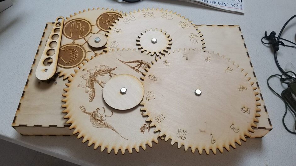
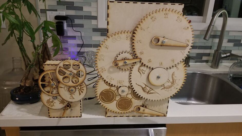
2nd verse, same as the first but…Shrank it by 50 % in x and y directions and changed the positions of the gears a tad.
Fixed a flaw in the gear ratios (what should have been a 15 tooth gear, was a 16 tooth gear)
Removed the numbers on the hour and minute gears and added holes to better see the underlying action
Changed the art to some zelda game graphics selected by my son.
cleaned up the electronics while i was at it…
9 Likes
Sweet! The arduino has plenty of time, so you could probably call the RTC on every step. And then even adjust your delay to get closer… (I did a toothbrushing timer once, but that just needed a stopwatch to see how far off it was and then some tweaking of numbers.)
1 Like
stepper increments of 200/rev suggest calling rtc every 3 seconds or 10 clicks.
Curious, I’m inept, and trying to make use of Inkscape. The gear renderer prints (I’m guessing) at 1 pixel line width. What do I do in Inkscape to make the “drawn line” print wider? I can barely see what I’m doing. Somewhere down the line I’d like to build a geared print with my Glowforge, right now I’m struggling to design.
Select your lines, then go to Object->fill and stroke.
You want to change the stroke style, you can change the width there.
It’s a good idea to explore that entire panel, it’s essential to styling anything vector.
2 Likes
Very Cool! I teach with the Arduino - we may have to try this!
that did the trick.Thanks evansd2!
Incredible outcome on this item!! I wonder how many hours that you invested in this one. Very Cool!!!