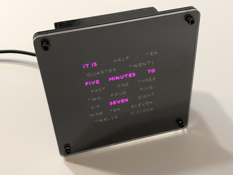
Build a word clock with just two parts. A Wemos D1 Arduino and an 8x8 RGB LED matrix.
Finally got around to posting the write up on instructables. (last day for the contest ![]() ) Have a look a drop me a vote. Thanks.
) Have a look a drop me a vote. Thanks.
Build a word clock with just two parts. A Wemos D1 Arduino and an 8x8 RGB LED matrix.
Finally got around to posting the write up on instructables. (last day for the contest ![]() ) Have a look a drop me a vote. Thanks.
) Have a look a drop me a vote. Thanks.
I may have jumped the gun. My entry has not been approved for the Arduino contest yet.
Nice.
Very nice. So the WEMOS ESP8266 does the control and power directly without having to think of powering the chip and the matrix with different voltage?
These components looks great. I have an ESP32 I’ve been messing with and wanting to do something but then I get into the question of driving the LEDs and then driving the chip and that means more components and figuring that out and more complexity. This is as simple as I’ve seen. Thanks for posting.
This is great! Hope it gets approved…
Not exactly. The 5v pin apparently isn’t tightly regulated, but it can apparently drive a good bit of current, enough to run these leds without any red shift from voltage drop. That being said I might run a +5 and ground to the other end of the led matrix to minimize voltage variation from LED #1 to LED #64.
By comparison: Arduinos tend to have much lower current ratings on their regulated 5v pins, so you might not want to try this with one of those.
(In no way am I trying to take away from this nice simple build, that’s its whole appeal, and it’s pretty slick. That being said there are some stability considerations that come into play here that don’t add a lot of complexity, which I’ll recommend below. Also I’m no EE, so if someone else is and wants to correct me please do so)
Bear in mind that esp data signals are 3.3v. While that does sometimes work with WS2812Bs, the more sure way is to use a proper level shifting chip to drive the data signal up to +5v. With short runs like this you’ll probably get away with it, but if your LEDs start to act weird I’d be very suspicious of the data voltage.
While we’re at it it’s also good practice to put a 500 ohm resistor on the data line. This helps prevent signal degradation, as I understand things.
Lastly it’s also good practice to place a 1000 microfarad capacitor across the power leads to the LEDs, it will stabilize the voltage and lead to fewer strangenesses.
I’ve had a 110-LED word clock running continuously for three or so years now, the capacitor and resistors were good insurance against power fluctuations. I’ve sold a good number of kits or completed clocks with the same configuration, I’ve had zero complaints about failures. If it ain’t broke… ![]()
Thank you for that explanation. That’s what I was thinking. I have the capacitors and the resistors, but I haven’t looked through my kit to see what I have for the level shifter.
I think one of the holdups for me is buying some of these other chips. They cost so little and then I only need one.
I would have gone with Adafruit, but I still haven’t been able to get my address validated for shipping. I get so far and then it kicks me out because I have a weird address thing. Then I haven’t kicked it up to the next level of support to actually have to interact with a human being to tell them that yes, this address does exist and yes, you can do UPS, FedEx or USPS.
This is one example of validation software that causes problems for the weird cases.
Seems strange to have a hold up on shipping, but that’s where I am.
I have been wanting to get into surface mount components and to some PCBs just for the experience, but then I haven’t found a good guide to how to order these components and what components. It gets complicated quickly when you start figuring the various size ranges.
Wow! Amazing! Well done!
Many chips are available on eBay, but you have to be careful of counterfeits.
I like Tayda electronics and sparkfun and amazon too. Googling around can find guides about which level shifters to order.
As for surface mount and pcbs…I never went down the surface mount path, I didn’t feel like getting an oven etc. I used osh park for my custom pcbs, and designed using eagle cad. There was a learning curve there for sure since I’m entirely self taught, but it was very satisfying. My first design was all done on stripboard though, for a project this size stripboards can work just fine and requires far less time and effort to complete.
But if we’re being really honest, this is about 4 components, you could probably just solder everything together without a pcb and then just hot glue the whole thing to a substrate to prevent stress on the wires. It’ll be ugly but it’ll work!
Of course… you’ll know. Maybe a nice clean pcb is in order ![]()
I have been very lucky. Most of the USB power adapters or power banks I have used have been perfect. I had one that was a bit wonky and caused the LEDs to flicker and shift. With only a few LED lit at a time and not a full intensity it seems to work fine. But then again I have no idea what I am doing. 
Yeah that is most likely either the 3.3v data signal or instability/noise in the 5v reference voltage, it’s hard to say which… my gut says data voltage, but you’d have to troubleshoot it. Heck it might be a bad matrix or ESP.
The data signal voltage issue is annoying but shouldn’t break anything. The voltage however… WS2812 LEDs are fairly fragile. If you supply more than about 6v to them you’ll fry them dead. USB is supposed to be 5v but it’s smart to test this if your power supply is from a new source. Quality control can be awful on these things.
I have bought 5v power supplies that were pushing 8v. Worse: I had a 9v supply that was pushing 16! Caveat emptor.
Lastly, a quick check of the voltage coming from the pins before you wire up the leds is probably a good idea, especially if the hardware you’re using is unproven.
Guess I’m ordering an Arduino
If you can wait, the ones from here are ridiculously cheap ($3.25 US each). If can’t wait a few weeks, then it’s ebay or amazon.
BTW it my project got accepted for the contest. Lots of great projects there too. Vote for them all.
Congrats! 
thanks for the link! I’m in no hurry, my forge isn’t even here yet, and it is KILLING me…lol
Voted. Your instructions were nice and clear. There are some pretty cool projects… I may have fallen down that rabbit hole this morning.