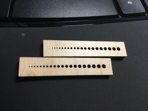
I am testing my Fusion360 to Inkscape to Glowforge work flow. At the same time, I made a pattern of test holes for deciding what axle hole sizes to use in my (future) gear designs.

15 Likes
That’s some tiny holes! 
1 Like
Wow - those are some time holes! The smallest I’ve cut were .09" on some maple hardwood; no problemo. But, that’s about the same as your biggest holes here!
I see yours go as small as .005" - how did it do with those?
1 Like
My test was on the medium maple as well. I can see light through even the smallest one. I’ll try (again) to get a picture to post. So far, I’ve been amazed by this machine.
18 Likes
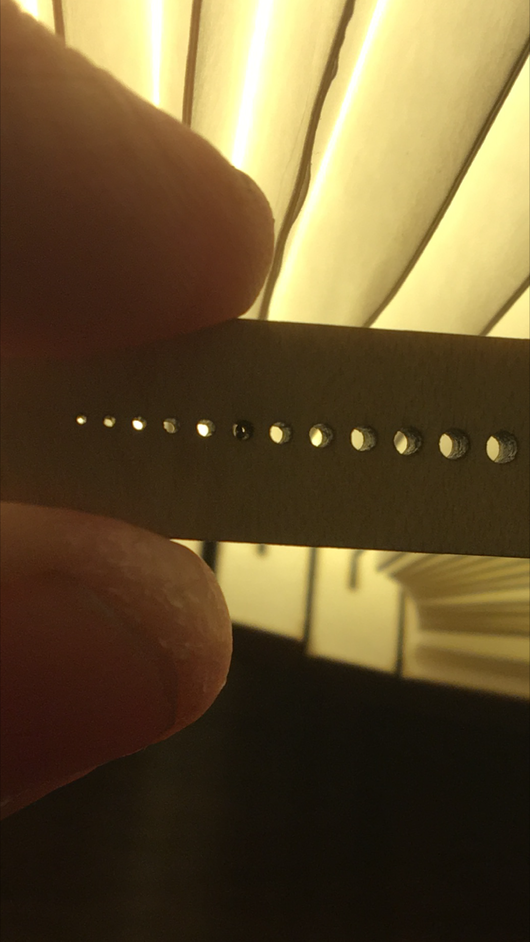
Got out the (standard) pin gages:
“0.1mm” = 0.012"
“0.2mm” = 0.016"
“0.3mm” = 0.019"
“0.4mm” = 0.021"
“0.5mm” = 0.024"
“0.6mm” = 0.029"
“0.7mm” = 0.033"
“0.8mm” = 0.037"
“0.9mm” = 0.040"
“1.0mm” = 0.045"
“1.1mm” = 0.049"
“1.2mm” = 0.052"
“1.3mm” = 0.056"
“1.4mm” = 0.060"
The average error of the larger holes was 0.005" or 0.13mm, which I assume is the effective beam diameter in this material. If hole diameters are designed this amount undersize, they will be very close.
A test of this sort probably should be done in the selected material and power settings if accuracy is important.
8 Likes
Interesting test - thanks for sharing your process and results!
1 Like