I am starting to organise introducing my daughter aged 13 to CAD for her GCSE (UK exam) in DT and trying to stay 1 step ahead in ramping up the level of difficulty. It’s proving to be a bit of mind twister as we have decided to focus on creating Japanese inspired Kumiko patterns. We are currently stuck CAD wise at doing patterns only using 90 degree angles so, squares, rectangles and L shapes that can interlock by being lazer cut.
Is there any CAD experts on the forum who might be able to help work out how to interlock patterns involving a 60, 120 degree and other angles?
We are doing it as separate bits, akin to the traditional style but using CAM. As patterns goes it’s really easy to create with lots of cultural references out there and by doing it in bits it teaches how to use CAD with simple shapes while visualising in a 3D space, as the interlocking bits become solid objects. It also ramps up the use of CAD features like constrains to aid with scaling up and down your base material choice
Using CAD can be a bit random for kids but mine loves seeing the machine make her stuff and she is slowly coming to understand just how powerful CAD can be
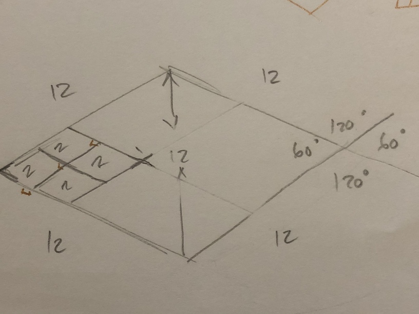
Now the issue is that once your item is no longer at 90 degree it won’t interlock anymore so we are currently unable to create any diamond shapes and diamond shapes are an integral part of Kumiko design
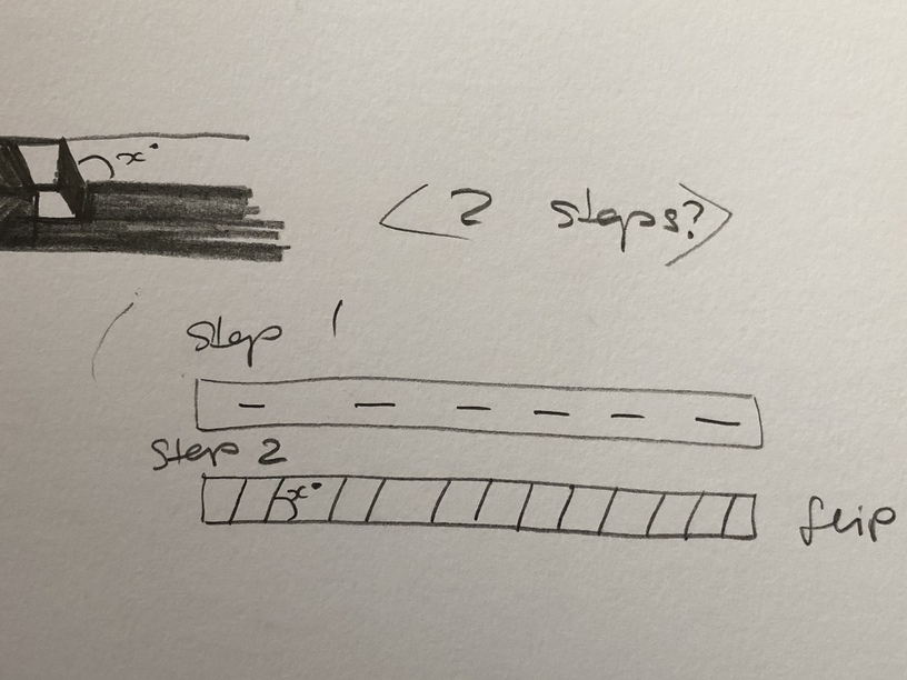
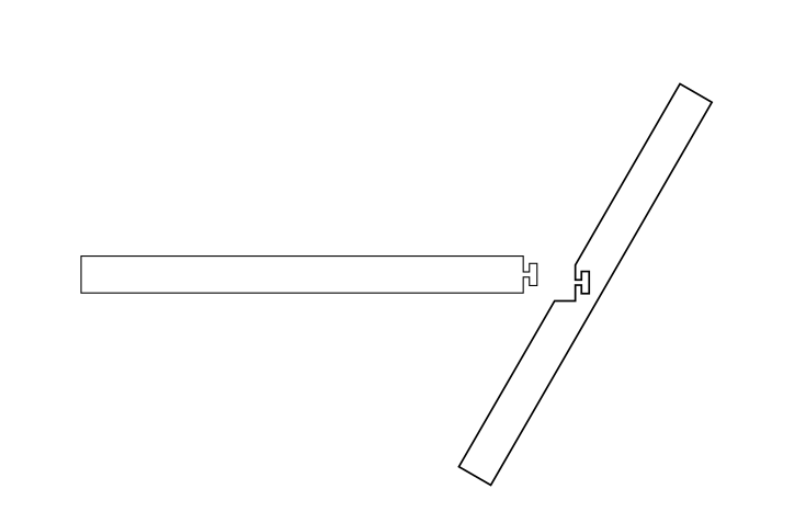
Okay, I think I get what you’re saying. You can’t make the slots angled using the GF. You’d have to just lengthen the slots enough to accommodate the angle of the crosspiece.
What CAD software are you using? I’ve done something similar in Fusion 360 where I positioned my parts at the angle I wanted, subtracted to make the slots, and then manually straightened the angled cuts to make a wider but 90º slot.
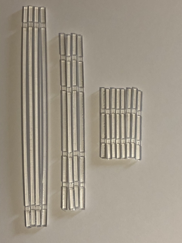
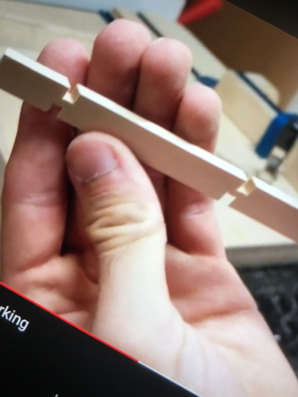
After @geek2nurse pointed the way I spent some rime wandering that rabbit warren and to go for real (in wood or acrylic) you would first need to cut the long sticks and rotate them so the width is side to side and cut the “V” grooves from that angle. With careful use of acrylic-cement, you could have a strong result, Or you could just do as she did and cut the design from a single sheet of material how it would have looked.
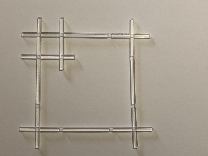
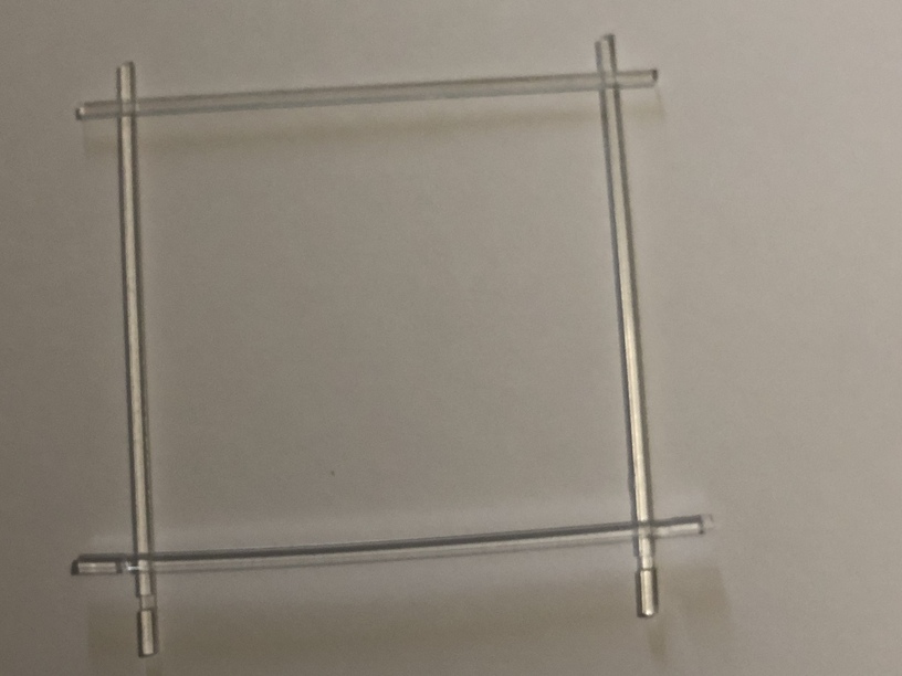
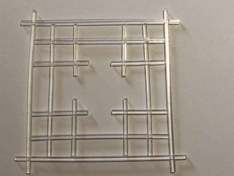
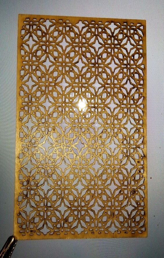
I went a different way and worked for designs made up of connected lines ignoring if they could be built using Kumiko techniques,
It’s totally easier to just create the patterns and have the lazer cut it out in one hit by using an SVG file
The challenge we need to explore is in the engineering aspect of breaking the design into its constituent parts and adding it to CAD; our daughter needs a reason to start using CAD basically and as she likes these geometric pattern, Kumiko was an interesting challenge to take up
It is indeed, but not one best suited to creating directly on the laser. You could, however, cut the pieces to size, and then use traditional techniques (saws, files, chisels) to make the required notches.
A laser is just one of many tools, it’s not the best tool for every task.
Indeed, but to interact many colors? Are you using Autocad? Have you studied Lisp? One great hint is that only the name of a block decides its geometry, and you can change that with Lisp so if block B is made of two blocks As and you explode it and then turn the block As into block B, etc.
You can also inlay different materials in different parts of a design, (as Kumiko frequently does) this might not be the best example and the colors would only be a reference for different materials but you get the idea…
If you wanted it to be built the old fashioned way then the old fashioned way with hand tools would do the best job, even if you used cad to lay it out.
We are using FreeCAD and not looked at Lisp. We are by far not professionals at CAD hence needing the help. I’m only just managing to stay a few steps ahead of my 13 year old
I have not used Freecad, but if it uses Lisp, by all means let them run that rabbit hole. Back when I was starting they were using Lisp to teach pre-literate children how to program. (Now that nas moved to “Alice” and much more complicated , but also a real rabbit hole with more of the complexities of modern programming)