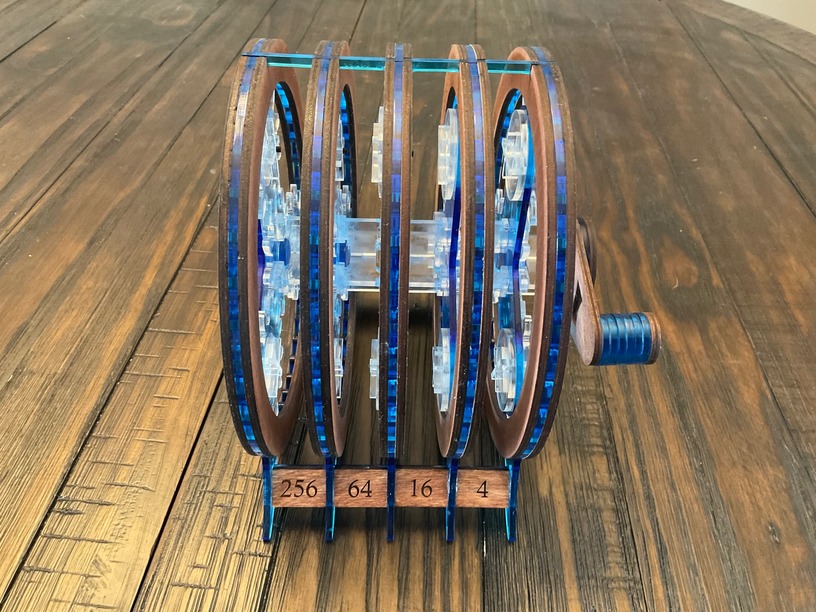
Saw a viral video somewhere of compounding gears ( https://youtu.be/5q-BH-tvxEg ). The gear reduction was so great that the last output of the last gear was into a brick, yet the gears kept spinning and spinning. I didn’t go quite to that extreme, but I thought that was a really cool visual so wanted to do my own thing.
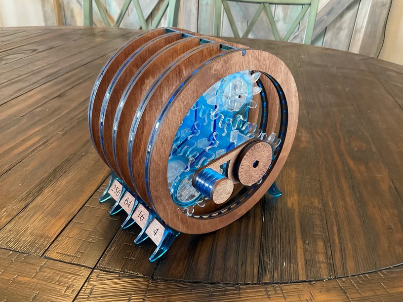
I made a gearset for a project a while back and found that involute gears weren’t great in acrylic because they would break at the root under load. I used round-tooth gears instead:
These gears could get much smaller in acrylic and take much higher loads. They also operated more smoothly than involute gears.
Of course, you’re multiplying torque as well as reducing speed.
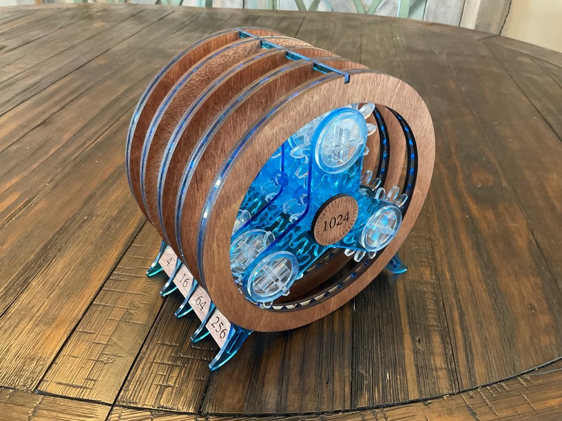
You should do something useful with that torque, like making an output stage that cracks nuts or something. With a 1:1024 stepdown, an ounce of torque at the crank would produce 64 pounds of torque at the output.
It will depend on how you distribute the forces. It isn’t the force so much as the contact pressure that will kill the acrylic. If you can distribute the force over a larger area (lower contact pressure) you can transmit the force effectively. Laminated gears would help with this, as would offsetting the teeth on a laminated gear, creating a crude helical gear that will help distribute the force over more contact points.
Yes, though you really reach a limit on the thickness quickly with the GF because of the angle of the cut face. It would be better to cut thinner pairs and laminate them so the cut edge angles cancel each other. Plus lamination allows offset teeth and you get more benefit than just extra strength.