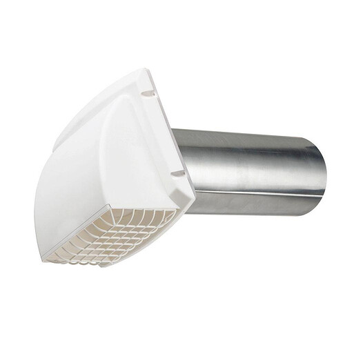
Awesome! Thanks for the help. ![]()
There are always going to be times when something won’t work if the needs of the design are changed. If you’ve used a loft, what happens if it’s discovered there needs to be three openings in a “Y” shape instead of two? Better to intersect the tubes and use fillets or meshes/patches at that point.
What if the openings do need to be concentric, but it turns out there needs to be a wall between the two openings? What if the tube needs a 270° loop? What if it turns out the intersection needs square edges after-all?
What if the inside cavity between the two openings needs to be spherical, with a square opening on the inlet, and an array of different size and shape holes on the outlet? Also, the outside of the tube needs to be heptagonal, with a variable-pitch helical groove running off-axis from end to end?
“Best”, seems to be subjective, at best.
It is ironical that I had a video waiting last night in which Lars first shows us how to do a shape, in this case, a cup, with the revolve and then, came back and did it with the shell command. The results were exactly the same but to me, the shell version would be easier to modify and maintain.
I also see where loft and sweep might be best for some use cases. So while I fully acknowledge I can’t appeal to authority as an advanced beginner, I’ll stick with “best” being somewhat subjective.
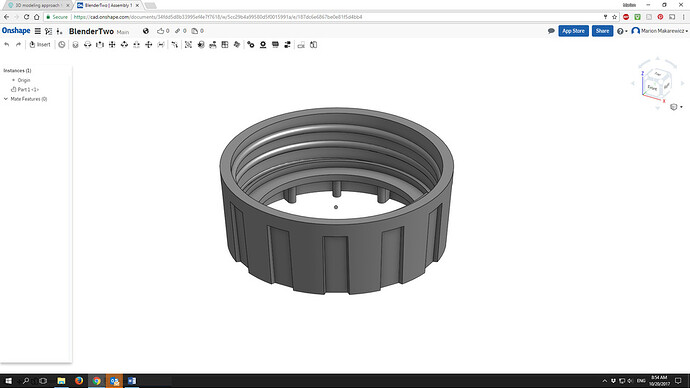
I was modeling this blade holder base for a blender in OnShape. I’m a novice but I can pretty well recreate any shape now. I made a very serviceable and accurate reproduction of the original blade ring. I used circles and extrudes and drafts and lofts. It looked great. It took a long time, all the while using a top down view.
After it was all completed, I was looking at the part from the side and it dawned on me that I needed to make a side profile and do a revolve. What had taken a couple hours in figuring out using drafts and lofts, took five minutes in side profile revolves.
The experience I gained from figuring out lofts and drafts was invaluable because I did need to use them to create the fixture detents so the base doesn’t spin inside the machine housing. But now I understand the purpose of design intent a lot better and have a sense of what tools are most efficient for me.
Like @mpipes, perhaps the word “best” isn’t the most useful way to describe any procedure. It is such an empty term. Once again, beware of labels because they simplify complex realities. Time-saving could be more accurate or most flexible method, or easier to make parametric.
In any case, I need to think about alternative construction methods, but first I have to be aware that they exist. Here is my OnShape document. I have to think about some of the design elements and procedures, but it’s defined well enough now that I can go back with the calipers and get better dimensions.
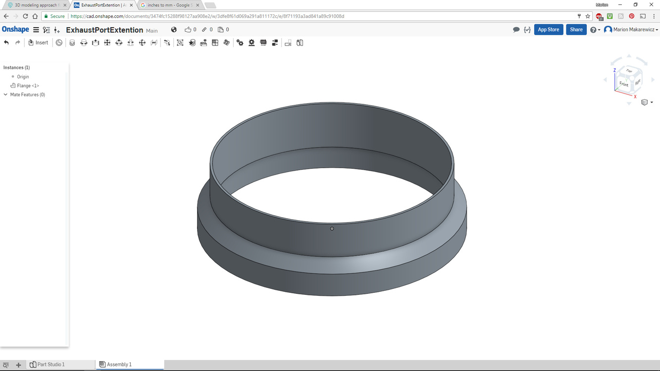
Comments and suggestions welcome.
So, here’s the thing, unless you count time using only, you are not a novice, you are a solid intermediate user. Doing that blender part shows that. If I ever get stuck and I think my question is general enough to translate to F360, you are someone I’d ask.
This is so true, I am a slower learner than you but I do learn and when I find out that something exists that is like a scalple when I’ve been using a sharp rock I am blown away.
Thanks. I think I graduated today. I have a fully defined sketch for the first time using OnShape. I’d be happy as a consult any time.
I would have never guessed this based on your end product. This shows everyone has their quick spots and their slow spots.
My finished files are not near as nice but I mostly won’t leave a sketch until F360 gives me the green light that it is fully defined. Too many weird things happen when I go to change something if I don’t.
Thank you in advance as I know that at some point I’ll take you up on this. We have a powerhouse of knowlage here. I PM’d @henryhbk just the other day about a question on using Alloy 910 as I knew he’d have an answer for me and of course he did.
I did give three completely different options …
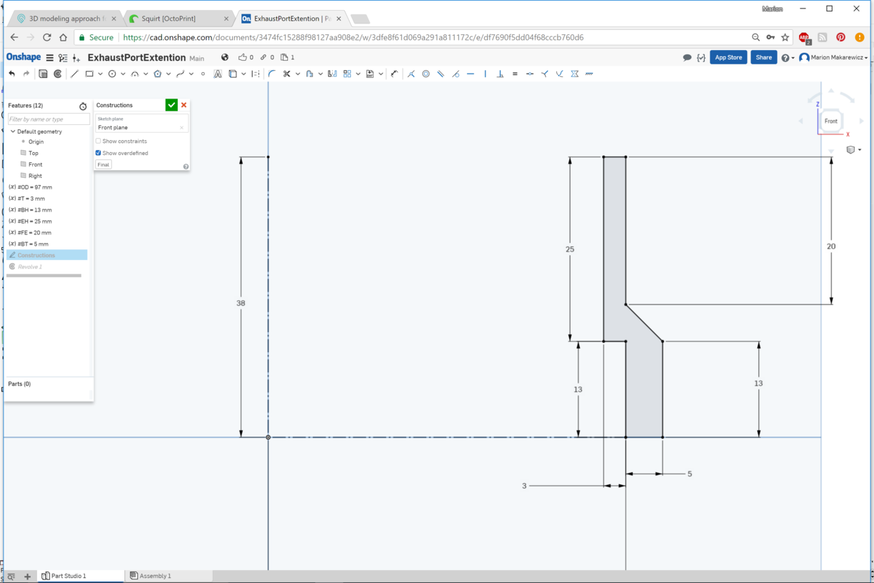
Some measurements for dialing in the flange extender.
I went with a 3mm thickness to account for the slight draft to the flange
I didn’t include ID for my variables. Just OD, thickness, flange base and flange extension, an inner dimension and an outer plus base thickness.
Used 97mm for OD.
The depth of the outer flange wall to case I used 13mm to not have it bottom out. Holds on snug with that amount of vcontact area.
The are 10.28mm around the bottom edge of the flange. So that limits the Base thickness. I used 5mm and that was enough. Used 3 perimeters and 25% infill and that seems sturdy enough.
Inside measure to span screen.
OnShape references:
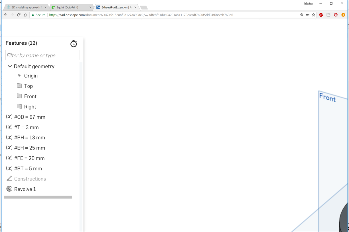
And final profile sketch before the revolve.
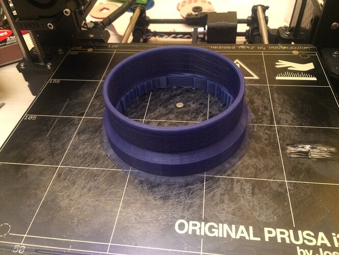
4 hours and 53 minute print. Opened up some new PLA from MatterHackers and it always seems that you have to do some waste printing or sacrifice some filament before everything works right. Had to cancel and start over as I had issues with the support sticking to the bed. Something is goofy there. This role of PLA is a bit bigger and with the full kilo to it, doesn’t seem to want to unwind easy and fast enough for the quick jerks of the support base. Need to read up on this condition. But it managed to stick down enough for the support base that I continued the print. Happy enough with it.
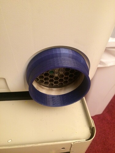
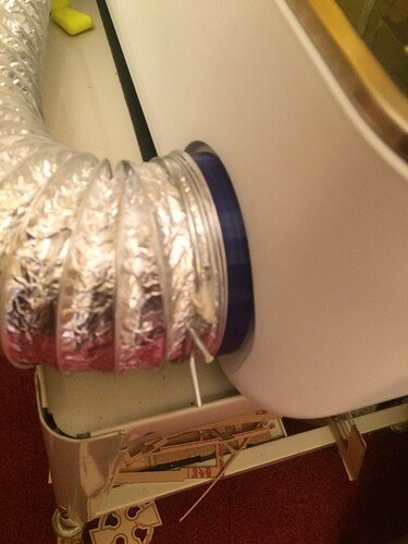
It works great. Cut a bunch of cardboard and didn’t encounter leaks. It sure makes connecting the dryer tube easy. Thanks @dwardio for the inspiration.
Here’s the STL zipped if anyone wants to use it. GFExhaustFlange.zip (8.7 KB)
Thats sweet! One question…why the sharp inside corner vs sloped like the outside?
Think of the turbulence generated over the flat edge of the Glowforge’s flange. You’ll have a triangular cavity around the perimeter where it meets with the diagonal of the inside of the extension. Just another spot for goop to gather. My design has a fairly smooth transition from original flange to extension. Possible to use some silicone to seal it, but as is now, it butts up very snuggly and allows for more surface area to seat into the extension.
Thank you for sharing the file! Going to print myself one.
No matter what I try, and how much foil tape I use, my Glowforge stinks up my shop immediately when I start cutting anything. I’ve suspected it’s that back exhaust and hope this will help.
If your run is greater than 8 foot (on the vent duct) and/or you have more than one 90 degree bend, the back pressure is too much for the GF ![]() internal fan (without an in-line booster).
internal fan (without an in-line booster).
I really do like the coupler that @marmak3261 has designed (Thanks Marion!) for getting a better connection to the GF ![]() .
.
As @PFI-Guy has said keeping the hose short and minimizing the number of bends in the pipe helps to reduce any back pressure in the exhaust.
Minor clarification. Folks have an unwise tendency to think in terms of absolutes and parse every sentence in the forum. My exhaust setup uses the provided 8ft hose with three 90degree bends and a gravity dryer style flap on the exhaust. So it’s not a completely unobstructed installation. I have ZERO smoke or smell entering the room during operation. The exhaust fan works quite well.
The number one smoke/smell problem is a failure to understand that the exhaust setup from fan to vent must be almost air tight. Any pinhole or ever so slight gap at the unit connection or the vent connection will leak. Mine did until I used foil tape to seal those two connections. Air gaps in the lid or front door are rarely the cause of smoke or smell during operation.
The run is about 4 feet, with TWO inline boosters…one at where it exits, and one mid way. Sigh. I’ve taped everything in sight but still must be missing a hole somewhere.
Booster fans are notorious for having leaky housings. You’d probably be better off without both of them!
edit: suggestion: hold a lit butane lighter near the housings and observe which way the flame deflects.
If you’re attaching anywhere to a preformed vent with a pipe then you should also tape the seam that runs the length of the metal piping too - it’s not sealed with the crimp connection they use.
That line on the bottom is where it crimps together and it leaks like a sieve ![]()
I am concerned that if it is 4 feet to the external exhaust vent and you have 2 boosters, something is very wrong.
10 years of commercial construction has taught me that simplicity brings success. So if you don’t mind, I would like to review with you your setup.
Couple of questions first.
-
If you are in a commercial building, when you enter the main doors (or even into the room where your GF
 is located) does the air come in to the building or room or go out from the building or room?
 -
Does the vent pipe to the outside go up to the ceiling/roof or horizontally through the exterior wall (meaning also, you can walk outside and feel and smell the exhaust from the GF
 ?
?
