Hi – I want to work up a design for an exhaust port extension for my GF. I understand why the current design was limited to ~15mm, but I continue having a hard time getting a good (odor-tight) seal at that end.
I have a 3D printer and figure I can easily print a female to male adapter fitting both the outside diameter of the GF exhaust and the inside diameter of hose/ducting.
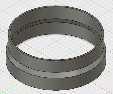
Using sketch-up, I can make two primitives with an appropriate wall thickness, one with the correct ID and the other with the correct OD and butt them together, but I’d like to fillet/smooth the interior join to prevent crud from building up.
Any suggestions? I’d rate my sketch-up skills at about 4/10 and my Fusion 360 skills at 1/10.
A fully parametric design (exhaust OD, input & output depths) would be ideal, making physical prototyping much easier to iterate.
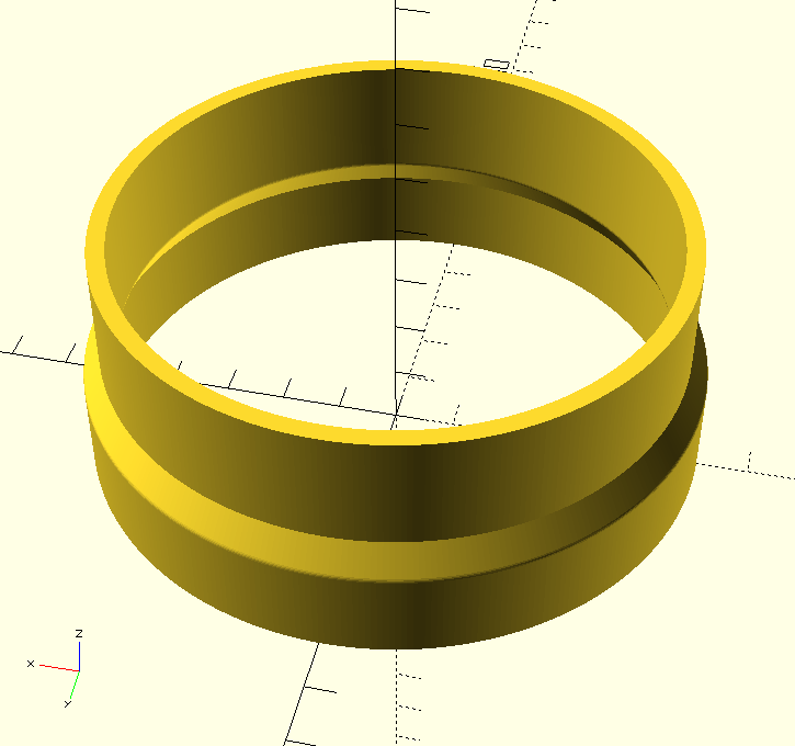
In Fusion 360, you can leave space between them and use “loft” to extrude from one profile to the other. Or, if there is enough space, you can select the interior edges you want to smooth and use the chamfer or fillet function.
For the loft option, I find it easier to model the whole assembly as a solid (rather than a hollow tube) and use “shell” at the end (and then punch through the other end with a cut extrusion) because “loft” gets squirrelly if the profiles are too complicated.
I’ve been wanting to do this for a while to make the connection a bit easier but I just don’t want to wrestle with taking the hose off to take the inner and outer dimensions measurements of the exhaust port.
What is ID and OD of the port as you measure? Definitely needs to be a precision measurement.
Honestly, I didn’t mean to step on your ego but the most knowledgeable people instructing in this say this and my admittedly limited experience bears that out.
Some things are certainly “best practice” but I’ve seen folk approach things completely differently than I would myself and it works for them.
For a single-body circular object, revolve is going to be tough to beat.
I wish Fusion 360 had SolidWorks’ cool dimensioning tweak where you can connect a dimension to and then pull beyond a construction line to double it.
(As shown at the beginning of this video…)
I’m not saying revolve is not the best way, it probably is, I’m just saying that when you are holding a hammer everything looks like a nail. I would not criticise anyone for approaching it another way unless I’m shown that the other ways have big pitfalls that revolve doesn’t.
I definitely agree that there are frequently multiple ways to get something done, but I also think there is almost as ferquently a single way that is “most right”.
I honestly don’t use revolves all that much, but I think that’s because I have some kind of aversion to creating an extra plane, which is a sometimes-necessary first step.
That would be a nice add. If memory serves me, AutoDESK Inventor had that feature as long as the revolving axis was specified as a centerline. Nice thing about the Fusion team is they’re constantly adding user requests like this.
“Best”
I could easily argue that the revolve command is NOT the best way to model this part parametrically.
Let’s say you discover a space constraint and you need the inlet and outlet to lie on non-parallel planes (ie it needs to be some form of elbow) or maybe both ends are parallel but the center points need to be shifted out of alignment with each other. Revolve can not do that, but Loft will.
Of course that takes a lot of forethought into the types of problems you can potentially run into, but that’s where 25 years in mechanical and structural design comes in.