I’m coming more and more to the conclusion that Affinity Designer isn’t as great for preparing cut files as Inkscape. Inkscape is basically a really fancy SVG editor, which is very handy for Glowforging. AD SVG export is more of a way to convert what you have on screen into SVG, which is not the same thing at all.
Case in point: I wanted to put a cut line around some objects, so I drew a no-fill rectangle around them and went to cut it. To my surprise, I had to convert engrave to cut, then the Glowforge took what looked like a double cut on the rectangle path. On closer inspection, it really took two separate cuts, leaving a tiny sliver outline.
What’s going on is that when AD converts a rectangle into SVG, it is actually converting it into two paths that represent the rectangle’s stroked shape as it appears in Designer, including all the miters or rounded corners and what not. When Inkscape does the same thing, it just spits out a single rectangle path and uses SVG style properties to record the stroke width, join styles, etc.
I’ve been looking for a way to get that behavior out of Designer. Convert to Curves does nothing useful in that regard, it ends up outputting the same stuff. Expand Stroke (called Stroke to Path in Inkscape) makes the double path thing explicit, so at least you can delete one of them, but that messes up your geometry. The easiest thing to do is to use a fill/no stroke rectangle (and move the layers around so that it’s in the background and not overlaying everything), which exports properly. Then you have to convert the engrave to a cut in the GFUI.
Just FYI, for fellow Designer users. I hate having to fire up X11 on a Mac, but once you get used to it, Inkscape turns out not to be half bad.
Interesting. I’ve been using Affinity Designer almost exclusively since my Glowforge arrived and I have yet to see the behavior you describe. In my experience, AD exports shapes pretty much just like Inkscape does. For example, I just created a simple document with a single very-widely-stroked rectangle (with mitered beveled joins for good measure) and got this in the heart of the svg:
GFUI ignores the stroke width (and beveled joins) and gives me a simple rectangle.
I’m trying to think of something that might be causing the behavior you’re seeing, but nothing comes to mind. If you create a new, empty Affinity Designer document, draw a single rectangle, and export to SVG do you see the same thing? What version of AD are you running?
AD has always produced reasonable SVG output for me. There are a bunch of options for SVG export (most of which are hidden behind a More Options button). What settings are you using?
Whoa. You are all correct, when I open a new document and export it, it does exactly the right thing. So that is good news.
So what is going on with this file? adtest.zip (5.2 KB)
Two rectangles, one filled one stroked. The filled one come out as a rect, the stroked as a complex path. Does the same thing happen for any of you with my file?
Yeah, looking at it in AI I see a solid blue rectangle and a black rectangular compound shape. It looks like AD is expanding the shape/stroking the path () of the rectangle.
That is what is so strange. I can’t duplicate the behavior in a new document. It only happens in this one, and I’m wondering what I did that makes it do that.
Very strange. I’m seeing the same thing in that particular document. Any stroked rectangle gets exported as though ‘stroke to path’ has been executed, even though it still shows up in the document as a regular rectangle.
I would guess that the .afdesign file is corrupted in some subtle way. How was it originally created? Did you import some other format or create it fresh with File > New? Either way, I’d say it’s time to submit a bug report to Serif.
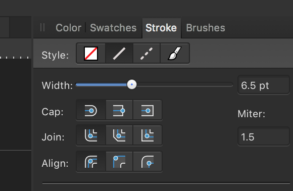
Found the problem! After much comparison between the two files, I noticed that I must have inadvertently clicked the “Align stroke to outside button” in the stroke menu at the top of the right hand window:
Anything other than Align to center (leftmost button) causes the bad behavior.
Heck, you could use that for kerf adjusting. Just set the stroke width to the width of the kerf, choose align to outside, then if you need to move the beam out around a shape, keep the outside path and delete the inside one.
If you are cutting a hole, you’d keep the inside line and delete the outside line. Bam! Kerf adjusted.
Similar to what happens in Inkscape, but that one is a bit of a pill due to some very weird constraints.
Ah. I guess that makes sense for mitered or rounded joins (the outside edge of the figure isn’t actually a rectangle in those cases). But for square joins, it seems like it should go back to the normal behavior. Good sleuthing!
You’d want the path aligned to the middle though, no? Having the stroke aligned to the outside would technically only be offsetting toward the outside, the inside line (which was the original line) would not be offset at all so therefore would not be kerf-adjusted.
Maybe purposely doing a stroke-to-path operation before exporting will become common practice, until Glowforge gets automated kerf adjustment implemented.
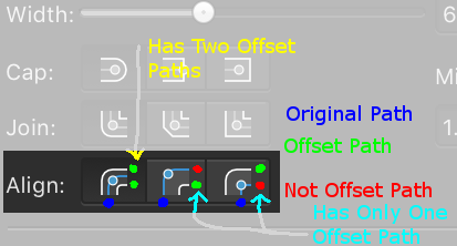
It looks like in AD, it’s creating two paths on either side of the stroke when you choose “Align to Outside”. Which would mean that the center of the laser beam would be traveling about half a kerf out from the center of the stroke path. (Kerf adjustment for the width of the laser beam, since the center of the laser beam will now be traveling a path exactly half a kerf out from the original.)
You just need to get rid of the unneeded one, which ever it is. (Not sure it’s possible to separate them.)
Yes that should work. The stroke appearance itself does not change. What happens is that “align stroke to outside” moves the nominal “path” to the inside. Only when it gets exported does the compound path conversion occur. You can certainly split and delete one explicitly though.
Not sure any of this is necessary though. I just tried cutting out an inch square and it measures perfectly to the limits of my measuring ability.
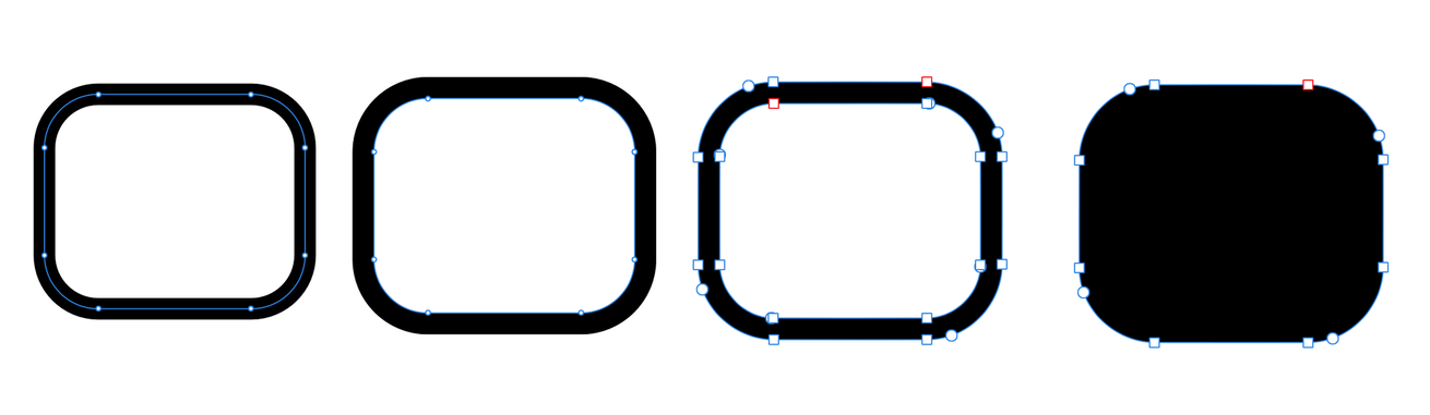
The box on the left is the original shape. It’s using the typical “Align to center” option for the stroke. The second one has been changed to “Align to outside” instead. The third has had an “Expand Stroke” operation performed, so it’s now a compound object with a fill (and no stroke). The fourth one has had the inner path deleted from the compound object. (At this point one would probably want to remove the fill and add back the stroke, albeit with the stroke aligned to center once more.)
 ) of the rectangle.