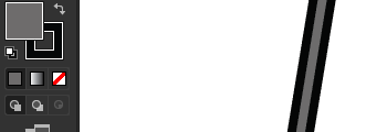
I have a dxf file that someone shared with me that I converted to svg via Fusion360. I loaded the svg into AI and I’m attempting to fill the paths (for an engrave), but I cannot get the path to fill…
I’ve attached a sample AI project with a piece I’m working on.test.ai (1.5 MB)
Also, if you converted to an SVG in F360 it probably did not join your lines. Ungroup everything in Illustrator and see if you can separate the parts by dragging them apart. If so, you’ll need to join your lines in order to fill the shapes.
@nathansouriyavong I tried selecting one of the numbers and doing an image trace (I’m assuming that is what you meant), but nothing is enabled for the image trace.
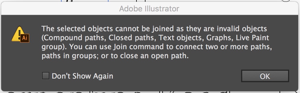
@Jules I tried ungrouping everything, then selecting one of the numbers (I see all the points), however when I select Object->Path->Join I get this dialog…
So I took a look at your file and have a few thoughts. First of all, this figure would be much easier and less work to just create it from scratch in Illustrator. But I’m guessing this is just an example of something more complicated that you would have trouble doing in Illustrator, so, moving on.
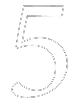
The figure “5” consists of a number of closed and stroked, filled paths as well as open paths, that are arranged to form the letter. If your goal is to fill the letter 5 with a color and have a consistent one-piece stroke on either side then you have a lot of work to do.
First, there were at least two copies of the figure 5, which you can see in Outline view. Select the top one and move it aside and you will see another. Delete the top one.
What remains is a collection of closed and open paths.
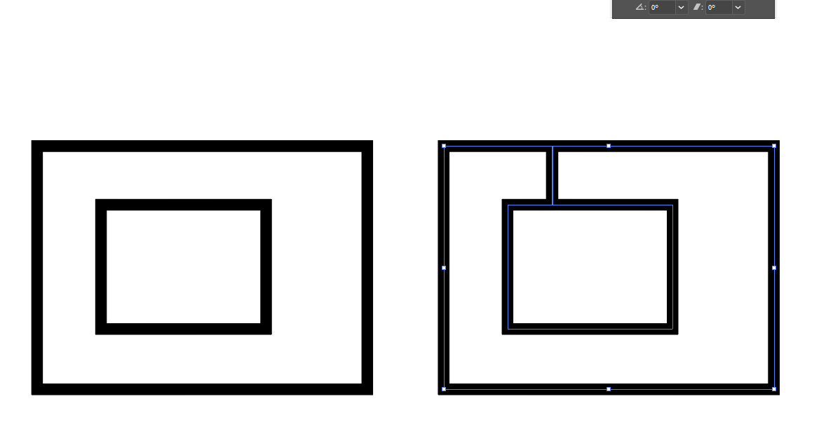
The open paths can be linked to each other with the Join command, but you can’t link them to the closed paths. I guess what I would do is, using the Direct Selection tool (open arrow), select the end paths of each of the closed paths and delete them, then join the remaining pieces to the other open paths. Below I did that, then filled the inner path with a blue color:
But it’s a lot of work for something that still looks a bit choppy (all the curves are straight line segments for instance). If I were you I’d use a different workflow. Have you tried opening the DXF directly in Illustrator? It might give you better results.
The file was given to me by a firend to try something that he does on his CNC, which accounts for the dxf. I’d recreate it, but that would mean I’d need to have the same font he used, and I was trying to work with what he provided.
I will try importing the dxf into AI directly and see what it does.
I imported the dxf via AI directly and it did make it somewhat easier. I am able to select and fill the letters and numbers.
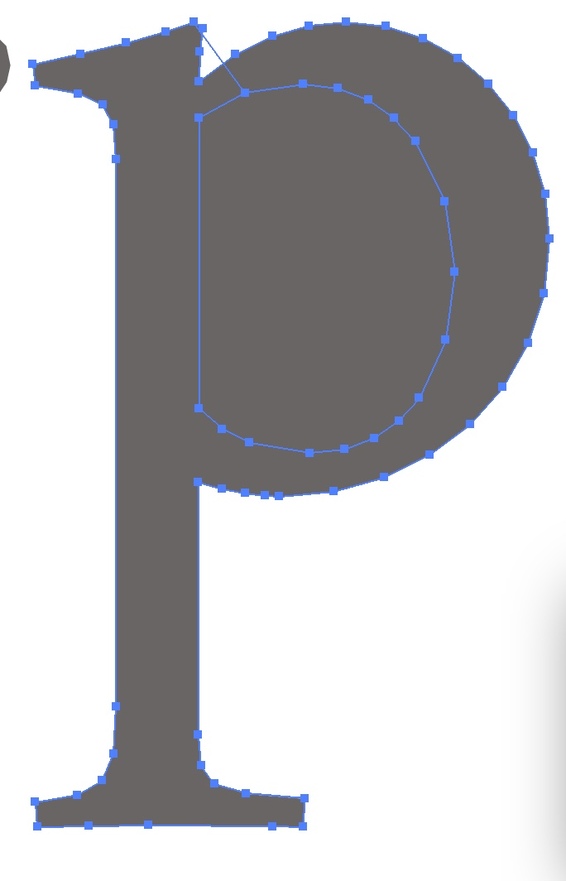
The final problem I see is that letters with holes in them are not filling properly (o,a,p,e etc)…
For example I tried selecting the anchors in this “P” and then join them, however I cannot seem to get the center not to fill. I tried not selecting the inner hole in the P but then it fills the entire shape…Any ideas on how I can open those areas? Thanks again!
I am by no means an Illustrator expert, being completely self taught, but I think what I would do is first, delete that extra path that crosses the top of the P, then try the various Pathfinder options (like Delete Front or Delete Back) until you get what you want. The end result should be a compound path that has the inner figure punched out from the outer figure.
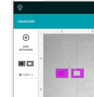
This was going to be my recommendation. In the long run though, I believe that the GF will interpret both paths to be filled. The GFUI reads a closed path as something to engrave within. So, even if you suibtract the center of the P, the GF will fill it. What I would do is a closed continuous path with a very small gap. See attached svg and screenshot of the GFUI interpretation. Test.zip (543 Bytes)
@scampa123 you may have taught me something today for non GF uses. I’m an architect by day and sometimes need to color, in Illustrator. The looping back is what I do for things like driveways or parking lots that have grass islands. Next time I’ll have to try the steps that you’ve listed.
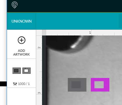
Actually, the GFUI interprets a Filled path as something to be engraved, even if the fill color is white.
If you have a null-fill inside a closed shape, the GFUI will not engrave it. That’s why surrounded empty shapes have to be part of a Compound Path, with null fill in the center area, in order for the GFUI to interpret it correctly.
Subtracting the shape out to make an empty fill area is the correct way to do it.