Alignment / Calibration

Agreed. And I disagree with the premise of this thread. Alignment with proofgrade is no better or worse than with material X - unless you’re a conspiracy theorist that believes Glowforge is hindering alignment for non-Proofgrade materials.

2 Likes

And the reason you (@zfam) believe the Glowforge is measurement is off is because you aren’t seeing the very left side of the material/bed. There is a “dead space” that is, I’m supposing, cropped from the raw bed image on the very left side of the bed that is about 7/8".

1 Like

I concur.

I am referring to the visual location positioning with the lid camera -after- you have done all the proper setups.

Easy enough on a fresh sheet of material, but locating a cut/engrave on a previously used piece of material is a pain the a**.

5 Likes

There’s an error in this part of your post…

Also, you should have positioned the wood in the same orientation in all the photos. And also placed it entirely within the FOV of the lid camera.

The lid camera can actually see the entire bed area, not just what is shown in the GFUI.

I am not sure what limitations are incurred as part of the de-warp process, but the original image is quite wide:

Versus what is shown in the GFUI:

11 Likes

Did a quick comparison between Proofgrade, and non-Proofgrade…

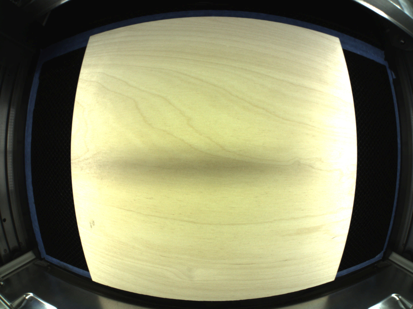
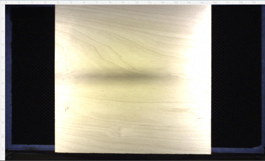
Baltic Birch from Woodpeckers (.115"):


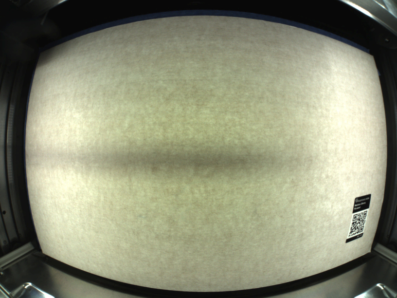
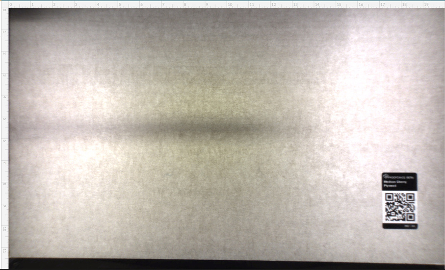
Proofgrade Medium Cherry Plywood:


10 Likes

With that level of distortion I’m surprised they have it down to 1/4. Dan has said that for that field of view at that distance required an expensive lens.

The camera may be able to see to the edges but given the distortion and lack of detail in the corners it doesn’t surprise me that the head position is not always recognized. I can’t easily see the head in these pictures. Gets lost and sometimes moves the head in the wrong direction during calibration.

1 Like

Yes the head is a black object lurking in a dark corner with only the right featureless end visible. I am surprised they didn’t but a white decal of some sort on that end

2 Likes

This function looks like it would sort out the calibration: https://docs.opencv.org/trunk/db/d58/group__calib3d__fisheye.html#gad626a78de2b1dae7489e152a5a5a89e1

Does anyone have a nice guide on how to work around the limitations of the camera and position accuracy?

I tried to get a engrave on both sides of the material by using score marks to adjust alignment to the part before starting the engrave. Even with several test score cuts to adjust position the resulting engrave is 1/8" off from intended position. Fortunately the part is salvageable but the fact that this didn’t work makes me confused about what is going on. It suggests that the camera calibration can vary even within the same app session and without power cycling the laser.

Using proofgrade birch plywood.

Why yes! @Jules has a lovely tutorial on that right here:

2 Likes

Read through the tutorial and I think this covers the basics but my concern is that any new upload or reset of the web app will invalidate any alignment you are trying to achieve. @Jules mentions this case. This means that any jig setup is invalid across different runs.

What I am looking for is how to realign a new cut against an existing surface reliably. The camera doesn’t work and there are no physical alignment options for material. You also can’t manually define the position of a cut relative to any 0,0 for the laser head. So some sort of test cut/score will be required.

preparing something for you… I believe you seek a “0.0 home location” correct? - even if you move, restart, turn the system off. You need it engraved at the same spot.

Design and layout your placement within your design software on a 12 x 20 artboard (the artboard size may not be a requirement…). It will load consistently in the GFUI and print accurately. No camera alignment required, just don’t move it.

Unfortunately this hasn’t been my experience. I left the material unmoved and was not able to get the alignment on a subsequent engrave to better than 1/8".

Let me see if I understand - you load a design, don’t drag it around, print it, reboot your Glowforge without opening moving the material, re-load the design, still don’t drag it anywhere, and re-print it. The new design appears 1/8" offset from the first one. Is that correct?

I believe the sequence of steps was:

  1. Cut and engraved a symmetric piece as single operation
  2. Turned off the machine, flipped the piece without moving the remaining material
  3. Turned back on and noticed image didn’t align with cut piece
  4. Went back to inkscape and added new score lines aligned with shape
  5. In glowforge app, scored these lines and ignored remaining vectors
  6. Scored lines didn’t appear aligned so adjusted pattern in app and scored again.
  7. Got what looked like good alignment, and started final engrave step
  8. Final engrave off by about .1" in the X direction

If you create your score lines at the same time as the original pattern elements up front, just giving them a different color, then ignore them for the first part of the operations, then flip, then score without changing anything on the screen, everything will align perfectly.

Even if it looks like the image on the screen has shifted halfway through, don’t move it. Just send the score, and set the first operations to Ignore.

3 Likes

I added the score lines to the original file and reuploaded for step (4) and I fail to understand why it would matter if I make them before or after the first pass cut. The geometry in the vector file shouldn’t be affected right?

What you describe is what I did in step (5) and they were not aligned with the existing cut.