One can see the alignment will be out when the outline of the board is not shown square.
Did anybody notice an improvement in accuracy in Dec? Examples like this seem just as bad as they ever were. The announcement implies there should be a big improvement if they have started using machine specific calibration data. Perhaps the machines shift in transit or need to be on a perfectly flat surface for the calibration data to be valid.
It would be interesting to see how it varies with a small shim under a corner.
I did not have my machine until Mid Dec so could not really tell you how much it improved. I can tell you that my machine is on a piece of solid Bamboo table that is both 100% level and flatter than I have the ability to measure. Those results I shared are with that taken into account.
I don’t remember what post it was in but I recall a conversation about the stickiness of the feet on the glowforge and the flex in the machine. At least one user said despite a flat and level surface, when they placed their glowforge the one foot stuck and caused some flex that they didn’t really notice until later but after picking that side up and carefully placing it back down so the flex was relieved, their camera alignment improved. Going from your post I’m sure you’ve already made sure of all these things but thought I’d throw it out there anyway just in case.
Just my 2d (UK) worth.
How many people check the flatness of the top surface of the crumb tray ?
When I was considering an early version of my vacuum bed insert for the tray, I realised that the design wouls only work if thre was no distortion cused to the honeycomb.
So a quick experiment - pressed down on it, and yes, it can be flexed.
Thanks @josephtpage you had me second guessing myself… just ran in and checked both of the foot pads are perfectly flat… was hoping I missed something and had an easy fix… no such luck.
Thanks!
When I first set up my new Pro unit I mapped it out and needed to do a 2 ticks right & 1 tick up move of my design vs where I wanted to align it on the material. Two weeks later I went to verify something for Support and repeated the alignment check but started with my 2R/1U adjustment and found I was off It’s now dead on - for my purposes…about 1/64" in horizontal which I can’t correct with an arrow key tick unless I zoom all the way in. Generally I don’t care about 64ths so I don’t bother.
why isn’t there a user calibration option?
it’s seems to be such a simple implementation, compared to the rest of the software developed so far. there are so many variables that would make a factory calibration inadequate, such as transport, bed level, temperature, trays manufacturing tolerances, degradation and many, many more: and any calibration, in any machine with moving parts will tend to drift over time. my inkjet printer can run a calibration or an autoalignment, why can’t my laser cutter?
there are so many ways this can be achieved, including the map above (which we can print on our own), a separate alignment jig, a test cut on draftboard… the engineers at GF don’t need my 2 cents on how to achieve this, but they do need to trust us, the users, the owners, with at least the option to calibrate our own machine.
The ease of dropping the design over a picture of my material is at the core of GF’s innovations, but if it is unreliable and doesn’t work the way we expect it to, it will cause more frustration than anything else!
Thanks everyone for your thoughts and contributions to this discussion.
@erin, the nudging solution is problematic. First the amount of nudge changes with the level of zoom, and second the error isn’t uniform. You’d need a nudge map just to know how much to nudge a design at any given location or zoom level.
@alexmcclure, it’s interesting your error map shows the error radiating from the center, while my error radiates from the center but is biased to the right (or left depending on what you use as the point of reference).
@josephtpage, thanks for the reminder about the table/feet situation. I will have try moving my GF to a more rigid table to see if that helps any. I suspect it won’t make too much of a difference considering the degree of the distortion, but I’ll take any improvement I can get until there is a more robust solution. Unfortunately, twisting of the frame doesn’t explain my center points being consistently shifted to the left about an 1/8th of an inch.
@leahgee2, I agree an at-home re-calibration procedure would be helpful. I wonder if the calibration is stored in firmware or if it is in the cloud and keyed to each unit by serial number. I would like to think Glowforge could ship a calibration map with the crumb tray. The user would just have take a picture of the map with the lid camera and then connect the center of the calibration map targets with a target overlay thus creating a vector map for properly de-fish-eyeing the camera. The calibration map could be photographed at multiple heights by stacking proof grade material under it.
Is that just in the centre or over the entire workspace?
I seem to remember @Jules has a very accurate machine as well but most people seem to have gross errors in the corners and rectangular sheets don’t look rectangular in the screen view.
My screen view changed quite a bit after the last update, and then it’s slowly been improving again, but it’s still off by about a quarter inch at the outside edges.
They’re obviously doing stuff behind the scenes that affect the placement alignment all the time. If everyone can just expect this kind of thing while they are working out the kinks, it won’t be quite so frightening. It’s not going to be like this forever, but it might be for a while. (Possibly months folks…they’re not going to get it fixed on our schedule.) Easiest to just work around it for the time being.
Thing is, unless I missed a statement to the contrary, that’s not the expectation Glowforge has defined… Specifically they state we can expect up to .25" disparity the farther from center. Seeing a disparity of anything greater than .25" should still be unexpected (and perhaps frightening) and Support should be notified.
Wasn’t talking about this specific case Tom, but I also don’t want people making incorrect statements regarding the status of certain machines (mine), which might scare people into thinking that there is something wrong with their machines if they have a slight variance in placement.
Mine has also been both good and bad at different times. The current standard is about 1/4" variance at the outside edges. More than that, and after you’ve checked to make sure that you have the tray seated correctly and that the lid is closed and the lens clean and the material isn’t warped and you entered the correct thickness for the material…then yes, support should be notified so they can check the metrics on it.
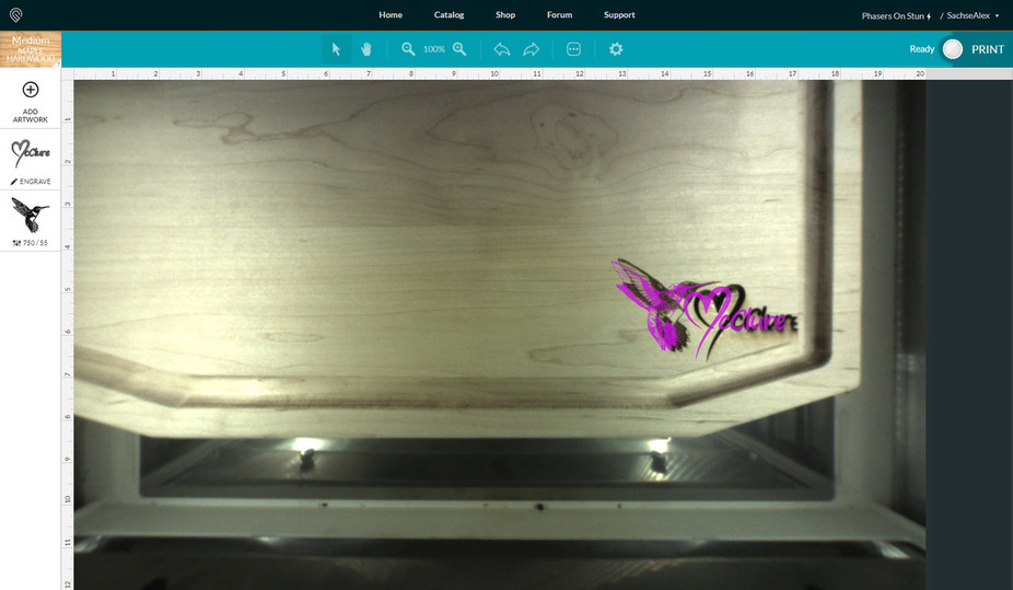
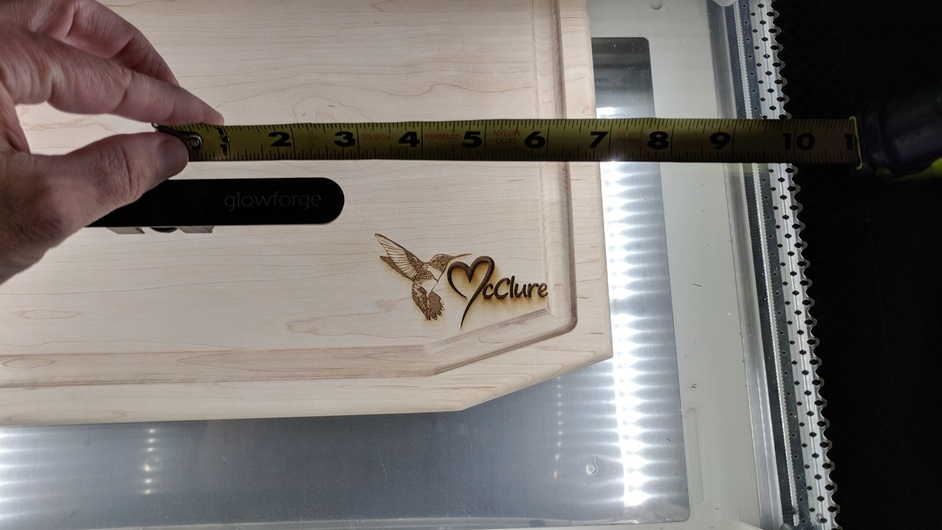
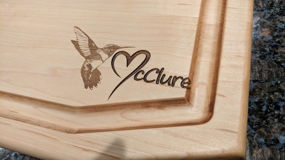
Last night at ~7pm CST I engraved my logo and an hummingbird onto a Cutting Board I made my wife. These boards already have 7hrs labor into them between assembly/X-Carve Routing/Sanding, so when I went to engrave them, I gave myself what I though was an extremely generous margin of laser error 1/2+" and even then it engraved off the board.
Material= Solid 1 1/4" Maple
Crumb tray removed
Set on 1/4" risers under Maple
Total material height from GF floor 1 1/2"
Cutting focus = 0.125"
Distance from camera to farthest edge of engrave 6" Distance from closest edge 3 1/4"
The engrave should have been well within the board surface and as you can see the “e” was carved off into the route edge.
Just an FYI. A minor error in material thickness could easily cause what you are seeing. Not saying your measurements are in error just that Support will ask you to test on known material and with a known design. Also, one user reported problem to a post is the rule.
So it seems to me that one could test the material thickness hypothesis thusly:
Engrave one of these test patterns onto, ideally, a piece of proofgrade (so as to eliminate questions about being outside of the allowable focus range – this should put it right in the sweet spot).
With the engraved sheet in the machine and the test pattern loaded in the UI, manually tweak the image height setting up and down to see if there is an offset that brings the two into close alignment.
In other words, rather than trying to guess the material height perfectly before engraving, experimentally determine it afterward. There should be a height that brings it into within the stated 1/4" tolerance.
I think I can confirm that. When my GF had to be replaced I was instructed to keep my crumb tray; I now use my original crumb tray in the replacement GF and my alignment has been pretty darn true.