I had to make my own graph paper, too…when cyndi first came up with this concept. I’ve just saved it on my computer so I can reprint anytime. As a matter of fact, I have my graph paper all ready to go in the GF right now…I haven’t done a placement test since that one first time. I want to see if it has changed any.
I printed out a new calibration map and taped it a piece of proof grade. The combined thickness of the proof grade and the calibration map was .139" as measured with a set of dial calipers.
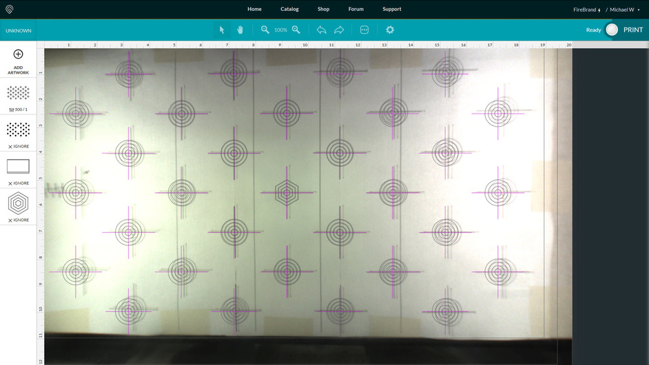
After manually aligning the hex crosshairs, the error between the crosshairs at the edges of the cut zone is approximately 1/4". From what I’ve read this is within the current accepted error range.

The post cut image shows no drift in either the lid camera image or the cut path overlay. However the cuts are all shifted approximately 1/8" to the right of their intended location. This is even true in the center.
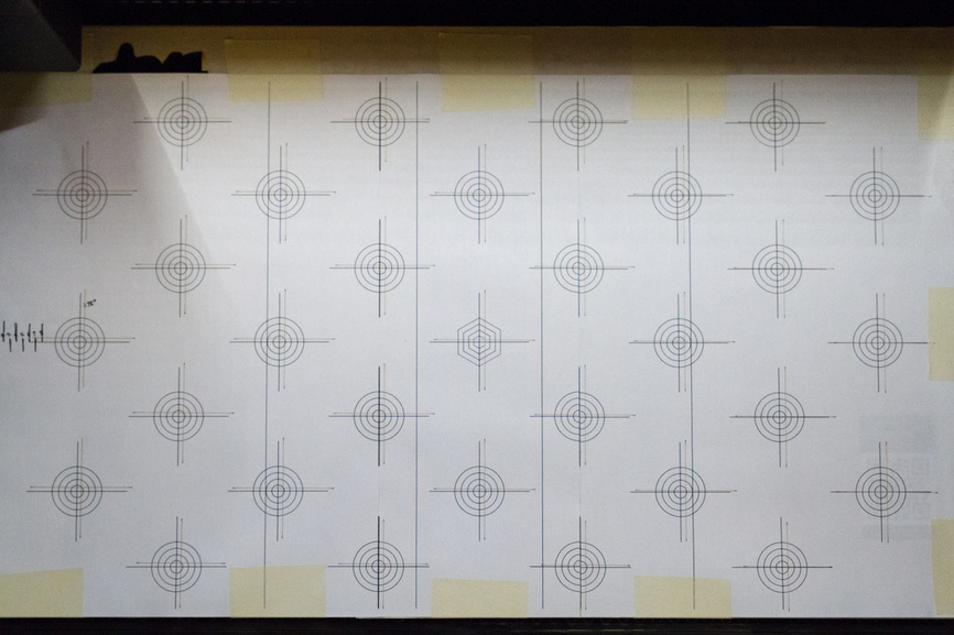
Here is a picture of the post cut calibration sheet taken with a DSLR and cleaned up in Light Room.
The gantry system is doing its job correctly, because all the cuts are the right size and consistently spaced. Unfortunately, the cuts are all approximately 1/8" to the right of where they should be according to the GFUI. This level of error seems high. Is there a way to add an X-offset to the lid camera image or to the gantry motion to correct this discrepancy?
2 Likes
Thanks everyone for an excellent conversation and for helping make this clear. @mike10, unfortunately, I don’t have a way to adjust for the discrepancy you’re seeing now, but I do expect it to improve over time. In the mean time, the suggestions above regarding jigs can be quite helpful when you want a precise print.
1 Like