I have two simple yes or no questions for either @dan or @Tony, whoever is available to answer them:
- Will the scenarios listed below work with the machine design as it is now?
- Is there an easier way to do it in the design that is currently available to us that I’ve missed?
Not asking for anything to be added that hasn’t already been long included in the functionality of the machine, and I’m not asking for details on how it’s done if there is a different way to do it.
If the answer to the first question is yes, and the second is no, then I will turn this into a tutorial later, with more information and screen shots from the Glowforge interface after I’ve seen it, so that new users will have a starting point for what they need to do if they run across one of these situations.
(Additions to the hopper have been discussed at length elsewhere. I’m just trying to lock down possible procedures for the newcomers. And I apologize for the length - I’m trying to keep it brief with little demo vids for now, and fewer diagrams.)
How I’m planning to do it currently:
This will be the work flow if I need to center text for engraving and cut a circle out of a sheet of material:
This should also work for perfectly centering a hole inside of a larger circle, with 100% accuracy and repeatability.
- Go into External Drawing Software and set up the circle at the size desired. (Illustrator, Inkscape, CorelDraw). I will also create the text and make it a different color than the circle.
A little demo of the process in AI: (takes about a minute and a half)
.
.
.
.
.

- Open the saved SVG file in the Glowforge software, and using the visual alignment, place the circles anywhere they fit on the sheet and engrave the text and cut the circle with the laser at the same time.
This will be the work flow if I forgot to cut the center hole in a wheel, or if I need to add a hole to a disk that is already cut out:
-
Go into External Drawing Software and set up the wheel with a centered hole (Illustrator, Inkscape, CorelDraw). I will make it the size I desire with specific dimensions at that time.
-
The outer circle will be the specific dimension of the disk or the wheel.
-
I will make certain to set different stroke colors for the two circles. (It becomes important for this procedure, which is creating a simple jig or template.)
.
.
.
.
.
-
Place a piece of material in the bed. (Cardboard, scrap wood, chipboard, thick foam…anything I want to use for the jig.)
-
Open the saved SVG file in the Glowforge software.
-
Turn off the center circle and cut the large circle out of the material.
-
Remove the center piece of material.
-
Place the disk into the hole in the template.
-
Turn off the large circle on the screen and cut the small center circle out of the disk.
This will be the work flow if I plan to re-use a jig for multiple or single items. Perhaps for engraving, or if I use a jig for alignment of a cut and plan to re-use it later at some future time.
It’s a double jig method that should give excellent accuracy. It does not rely on either camera for placement, but uses physical stops and limits, and mostly eliminates the need to align with the camera.
- Step one is to create stops for the machine. This can either be a large piece of wood pressed against the front and left side of the machine, with the rectangular movement limits of the machine removed from it by cutting out a large box or “L” shape.
(@Tony, I’m going to borrow your pic for now if that’s okay - it takes a while to put all of this together.)
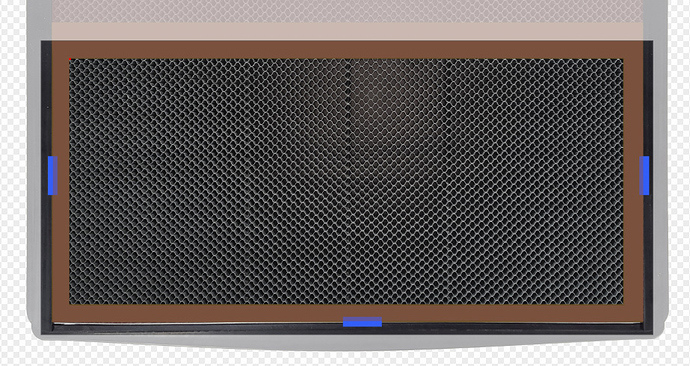
The little red dot is the origin. By aligning the material along the two sides attached to the origin point, a physical 3-Point registration system is created. This is the first jig. (Or stops, or whatever you want to call it.)
- Go into External Drawing Software and create your second jig with cutouts that follow the shape of your widgets and engraving included on it.
Draw a rectangle around all of the parts of the jig.
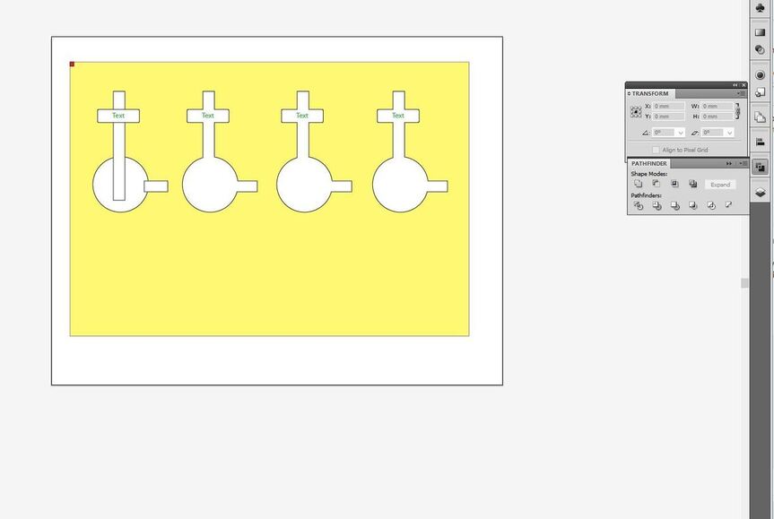
Save the file as an SVG.
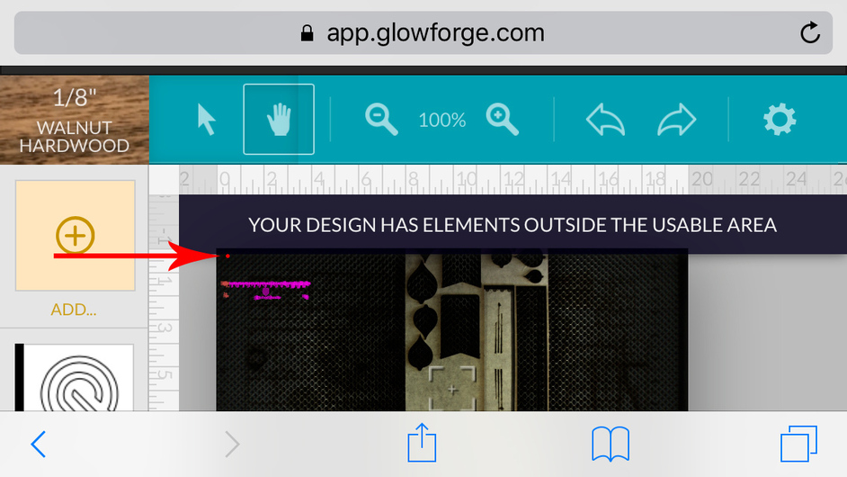
- Physically place the yellow jig material in the machine so that it butts up into the corner at the origin, against the original jig.
(This is the one place where we might have to use the camera - it depends on whether or not there is an upper left movement limit shown on the screen in the GF software interface.)
- Align the upper left corner of the yellow jig with the origin point in jig one on the GF interface screen. (Head camera? for tight focus?)
Okay…I lied…@Tony, if it would be less difficult to add a small dot on the interface screen that defines the upper left limit of the range of motion of the head, than it would be to completely rewrite the code to calculate movement based on a real 3-Point Registration system, it might be a nice addition, because it will make this much more accurate. Something for the hopper.
- Cut out the yellow jig material, including the outer rectangle, with the material butted up against the first jig, or overlapping it.
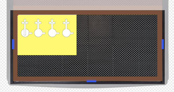
- Put the widgets in and run the engrave.
The next time you need to use the second jig, you butt it up against the stops again, and everything should still be lined up properly.*
*Update after testing Pre-Release unit: The placement information is not saved. This last will not work if you close the program.
So how far off am I? (Thanks for looking.)

