I thought about that, which is why I threw in the ‘gear it properly’, because getting the right height for the laser with different objects will be a bit of an issue unless you build small rollers that are geared correctly to provide the proper amount of rotation while still allowing height adjustments. The next question is if you can attach a right angle mirror to the bottom of the laser output block on the glowforge to convert your horizontal space into vertical space…
1 Like
I’ve seen a few different ways rotaries deal with oddly shaped cylinders. One used a pair of rollers on either end kept the same diameter, but used a scissor-lift on the narrower side to raise the rollers towards the smaller endpoint of the cylinder. Another went more with a lathe approach, squeezing between a single rotating roller on one side and a cone-shaped roller on the other. Neither required special gearing to maintain synchronous rotation, from what I could tell.
I know this is a year-old thread, but I think this fits best here.
My idea for a rotary device that does not require any mods to the gf. It would not rotate continuously, but in steps. Your design would be split into sections of a width that corresponded to the max adjustable focus depth of the laser, and those would be split into as many layers as needed to get around the material then stacked on top of each other. So if you had a 1"-round shotglass, and the GF can adjust focus within 1/2" you could very well get away with splitting an image in thirds, and having the device rotate the shotglass 120° after each pass. If that distorts too much at the edges, perhaps the image needs to be split into 6 parts, and the shotglass rotates 60° with each press of the controller button. Engrave one layer, rotate the correct number of degrees using a controller that feeds out through the pass-through slot on a pro (or make it battery powered and a wireless controller for the basic), engrave the next layer, rotate, repeat.
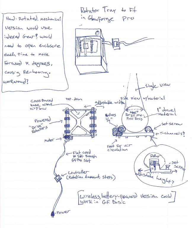
I guess, in theory, the GF could broadcast a control signal to a wireless controller that would tell it how to move it continuously, and and do one-step cylindrical objects, but I am looking for a way to make a stand-alone device that requires no mods and no additional work on the part of the GF team.
12 Likes
the stepper motors for the Y position are in the front end of the case. I havent attempted yet, but the belts can probably be pretty easily removed from those motors and belts from a rotary attached to them to allow for the GF to control rotation without it knowing.
The only issue I can see with this method is that before cuts, it goes to the center, right under the camera to do a few checks. If not sure what will happen if it doesnt make it there lol
4 Likes
You could even do this version by hand with a circular/cylindrical jig to hold your object. Score little angle markers on the end circles and line them up with a mark on the holder (using a magnifying glass).
You’d be limited to the 2" Z depth under the head, but that would be OK for some things. Also, for a 2" object, that half-inch focus range gets you 60 degrees from center on each side, which is 1/3 of a circle and might be enough for a lot of applications. Although there would be distortion and power issues as you got away from the perpendicular.
Has anyone with a pre-release tried engraving a small round object with autofocus?
5 Likes
My first thought (some time ago) was in line with this, using an indexed mechanical thumbwheel. By skipping the motor, controller, etc it is obviously cheaper and easier to build, and will take up less room. My concern was that this would require opening the lid between each pass, which would trigger a new homing cycle. So then I started thinking about ways to operate it through the pass-through slot. A drive-shaft from an r/c truck could work, but might be awkward as a rigid/semi-rigid assembly. I had not thought of a drive cable before, but that might work as well.
2 Likes
Ah. Good point. In that case I’d go with the battery-op version, maybe with a stepper, maybe with a servo that could do a ratchet for positive positioning. Easy enough to shield the parts that need not to be damaged.
For control: some kind of photosensor behind a diffusive shield for protection, located at an obvious point on the device. You would include a tiny circular engrave, to be cut 1% greyscale at 1% power (or whatever works) after the main engraving of that layer is finished. So the GF itself would tell the device it was done with the current orientation.
2 Likes
that would be a wonderfully tricky solution.
2 Likes
For a potentially bad solution. I’ve heard rumors that the switches on the front door can be “defeated” so that you can run the laser with the front door open (lid still closed). This was made in suggestion for if you had a 2x4 or something similar that you just wanted to engrave something at the top (or bottom) and it was too long for the bed size.
MAYBE you can get it so you can open the front without opening the lid and triggering the homing sequence.
(YES, operating this with the front door open is potentially very stupid. You are pointing the laser at the front of the machine which is now open…1. you now need to wear your safety glasses, 2. don’t stand in front of the beam, 3. look for burning holes in the wall opposite your machine.)
As I said, and potentially very bad suggestion
1 Like
Very, very bad. But the size of things you could rotary-engrave increases exponentially. 
That is the kind of thing I am smart enough to know that I am too stupid to do safely.
4 Likes
My idea above does not change the direction of the laser. It would not alter or modify the GF in any way whatsoever. It could be combined with some of the other ideas (like a different laser head that points at an angle for potential larger objects) but does not need to be. That is really the main point of the exercise for me. I do have vague hopes that someone with actual mechanical knowledge takes my half-baked idea and cooks it the rest of the way.
@paulw I know what my luck is like. I have spent much time with Murphy, examining his Law. If I try to bypass the interlocks and work with the door open, there will be an earthquake that will put my face inside the machine.
4 Likes
I’d suggest not trying to engrave hard drive platters with the door open. They are apparently very effective CO2 laser mirrors.
3 Likes
I have heard that as well.
I have two pairs of L.E.P., and my GFPro will be installed in a room with no windows, concrete floors, cement walls, and a commercial fire-suppression system… and still I have absolutely no plans to be working with the door open, nor with hard drive platters.
Risks aside, I can’t see having the door open as being anything other than a massive air leak. Does the ventilation even work with door open? I’m not the one who will attempt to determine that!
2 Likes
It will certainly keep running (since it doesn’t know the door is open), but the airflow pattern will likely be all messed up. And it will probably fill your room with fumes, too!
It must - the Pro is designed to have the pass-thru doors open.
Or were you thinking of the lid?
I was thinking about the front “garage door”, not the pass-through slot itself.
The pass-through slot does not have a door, it is covered by a flap of some sort.
1 Like
You could sync the rotation by advancing the rotation 1 step (with a stepper motor drive) for every “left to right” head excursion.
2 Likes
I am in the same boat. I ordered the basic with the filter, but will have to vent out the garage door until the filter arrives. I guess I will have to stick the hose under the door. Not sure how this will work. 
1 Like
if you have a sectional/roll-up then it won’t be too hard to figure out a vent section that you could put on the floor. It could be as simple as a 2x6 with dryer fitting, or it could be framed, insulated, skinned, fold in half or in thirds for storage…
Not sure how I would go about doing it with 1-piece tilt-up door, or with barn-doors.
4 Likes