Arduino/RPi/Etc + Glowforge projects

Continuing the discussion from It was certainly a "Maker" holiday this year!:

It seems that there are quite a few people on here that have, at the very least, an interest in projects involving things like the Arduino. Have people come up with ideas yet? Post them here!

I’m typing mine now. It’ll be a reply shortly.

13 Likes

I’ll definitely be building small cases and the like for small controllers like the Pi. Mounts and lever arms for servos are also fair game!

4 Likes

When you can combine “smart” with making the physical the possibilities are ENDLESS.

One of a thousand things I want to make is a smart desk lamp. Servos or stepper motors, light where you need it all the time.

5 Likes

I have four early versions of the raspberry pi and none of them have cases. There are many designs, just need to take the time to print them.

3 Likes

Bought my 12 yo son an arduino kit with lots of extras…he’s already surpassed my understanding…lol. Already has lots of ideas for things to do and a list of additional components wanted. (In fact I just went into his room tonight to check on him and he was mumbling, in his sleep, about needing a certain component…lol)
This is what I got him in addition to a number of various sensors.

Geekcreit™ UNO Basic Starter Learning Kit Upgrade Version For Arduino
https://banggood.app.link/pJP72RM3zy

Would love to see what others are doing :slight_smile:

12 Likes

So, my youngest brother got me in the gift exchange that we brothers do every Christmas. He’s been listening to me gab about the Glowforge since I made the pre-purchase. He got me a couple of sheets of 12"x12" acrylic after scouring the Glowforge sales site for info on what it could do. He even accidentally got cast rather than extruded.

I have had an Arduino, an ultrasonic sensor, some female jumper wires sitting around for a couple of years. I recently ordered a relay board to add on. Finally, I’ve come up with a project with some help and inspiration from the acrylic. Also note that I am an absolute beginner and have next to no programming or electronics experience to speak of. Thank goodness for the internet.

I want to use the sensor to create virtual “buttons.” Using a “WHILE” statement, I tell it to do different things depending on the distance detected by the sensor. Here’s the relay switching a different number of times based on how far away my hand is.

It’s a bit more obvious with sound and the last one is 4 quick blips on purpose, just for experimental purposes. You’ll see a light that stays powered on the Arduino and turns off when the relay is switch and it’s light blinks. For whatever reason, sending a “low” signal is what makes the relay go. I’ve got it all plugged in to the header for ICSP (AKA ISP?) so that I can use the female jumpers I have. The relay is on pin 13, which is also the on board LED, which is also available through the ICSP header. The only place I had to use loose wire was to power the relay board. That’s the red and black wires going to the normal 5V and ground. I can use this with an extension cord wired through one of the relays to turn on and off anything with a plug.

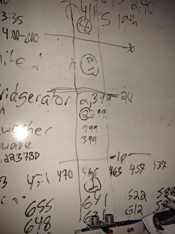
Initially, I didn’t have the relay board and was just blinking the light. Here’s my test setup:

Each rectangle is 10cm. Touch the circled number 1, one blink. 2, you get two. Et Cetera. The sensor is in the bottom of the picture.

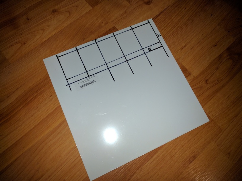
Here’s the acrylic my brother got me:

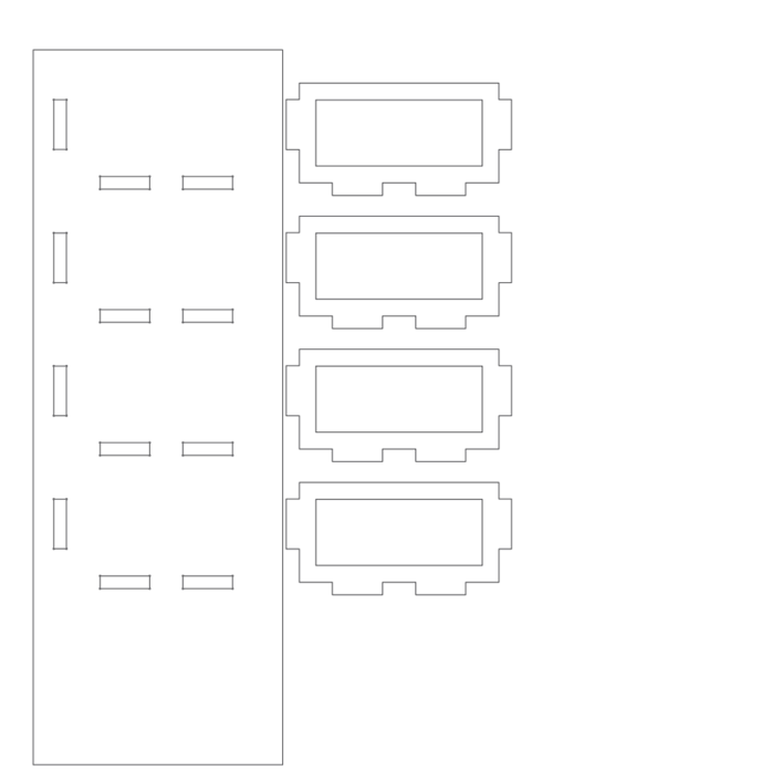
I’ve sketched out distances on here to get a feel for their size. There’s a protective covering that will be removed before cutting, of course. There will be rectangular dividers separating each “button” with smaller rectangles cut out of the inside to allow the sensor to pass through but provide definite spaces for a user to “press.”

I’ll create a housing around the sensor and put the Arduino in an enclosed area underneath. Probably will add LEDs to light the “button” from the top or bottom to provide indication of a detected “press.” Could be a version of the game Simon. Could have cards in each space to show what sound will play. Don’t really care at this point. Kinda like Glowforge, I’ll put together some good hardware, then worry about finishing the software.

Here’s the code:

#include <NewPing.h>
#define TRIGGER_PIN  12  // Arduino pin tied to trigger pin on the ultrasonic sensor.
#define ECHO_PIN     11  // Arduino pin tied to echo pin on the ultrasonic sensor.
#define MAX_DISTANCE 45 // Maximum distance we want to ping for (in centimeters). Maximum sensor distance is rated at 400-500cm.

int led = 13;  //pin for built-in LED
NewPing sonar(TRIGGER_PIN, ECHO_PIN, MAX_DISTANCE); // NewPing setup of pins and maximum distance.

void setup() {
  pinMode(led, OUTPUT);
//  Serial.begin(115200); // Open serial monitor at 115200 baud to see ping results.
}

void loop() {
  delay(50);                     // Wait 50ms between pings (about 20 pings/sec). 29ms should be the shortest delay between pings.
    while ((sonar.ping_cm() > 32) && (sonar.ping_cm()) < 38)
  {
    digitalWrite(led, LOW);   // turn the LED on (HIGH is the voltage level)
    delay(50);               // wait for a second
    digitalWrite(led, HIGH);    // turn the LED off by making the voltage LOW
    delay(50);               // wait for a second
    digitalWrite(led, LOW);   // turn the LED on (HIGH is the voltage level)
    delay(50);               // wait for a second
    digitalWrite(led, HIGH);    // turn the LED off by making the voltage LOW
    delay(50);               // wait for a second
    digitalWrite(led, LOW);   // turn the LED on (HIGH is the voltage level)
    delay(50);               // wait for a second
    digitalWrite(led, HIGH);    // turn the LED off by making the voltage LOW
    delay(50);               // wait for a second
    digitalWrite(led, LOW);   // turn the LED on (HIGH is the voltage level)
    delay(50);               // wait for a second
    digitalWrite(led, HIGH);    // turn the LED off by making the voltage LOW
    delay(1000);               // wait for a second
  }
    while ((sonar.ping_cm() > 22) && (sonar.ping_cm()) < 28)
  {
    digitalWrite(led, LOW);   // turn the LED on (HIGH is the voltage level)
    delay(100);               // wait for a second
    digitalWrite(led, HIGH);    // turn the LED off by making the voltage LOW
    delay(500);               // wait for a second
    digitalWrite(led, LOW);   // turn the LED on (HIGH is the voltage level)
    delay(100);               // wait for a second
    digitalWrite(led, HIGH);    // turn the LED off by making the voltage LOW
    delay(500);               // wait for a second
    digitalWrite(led, LOW);   // turn the LED on (HIGH is the voltage level)
    delay(100);               // wait for a second
    digitalWrite(led, HIGH);    // turn the LED off by making the voltage LOW
    delay(1000);               // wait for a second
  }
    while ((sonar.ping_cm() > 12) && (sonar.ping_cm()) < 18)
  {
    digitalWrite(led, LOW);   // turn the LED on (HIGH is the voltage level)
    delay(100);               // wait for a second
    digitalWrite(led, HIGH);    // turn the LED off by making the voltage LOW
    delay(500);               // wait for a second
    digitalWrite(led, LOW);   // turn the LED on (HIGH is the voltage level)
    delay(100);               // wait for a second
    digitalWrite(led, HIGH);   // turn the LED off by making the voltage LOW
    delay(1000);               // wait for a second
  }
    while ((sonar.ping_cm() > 2) && (sonar.ping_cm()) < 18)
  {
    digitalWrite(led, LOW);   // turn the LED on (HIGH is the voltage level)
    delay(100);               // wait for a second
    digitalWrite(led, HIGH);    // turn the LED off by making the voltage LOW
    delay(1000);               // wait for a second
  }
}

I know there’s probably better ways to do that, but it’s my first project. Any tips, especially on code, are welcome. I used the NewPing library to run the sensor.

13 Likes

With the boom of the Nintendo Mini, I’m planning to buy a Raspberry Pi 3 and install RetroPie. After that, design a cool case, maybe arcade style. :grinning:

3 Likes

Here’s the start of a design for the acrylic:

Basically, it’s the button dividers with a path for the ultrasonic sensor. The space on the left of the slots that are on the side of the big piece is for little LED strip segments. Mine have 3 lights per segment. There’s a “button” and space for the sensor on the bottom. Also, I’ll add some tabs to the outside of the main piece so that sides can be attached. The sides will go below this main piece to create the space below for the arduino. I created “dogbones” for all of the slots, but don’t really know how to do it right or how “right” it has to be.

Lot’s left to do, but I’ve got to try and get some rest. I’ll keep posting as I go.

6 Likes

I have bunches of servos and motors and steppers that I’ve acquired over the years, so I think a big thing is going to be gears and racks and custom mounts (which can be 3D printed, but it’s a pain to get right). I wonder how small a rack/gear I can cut. Also housings for gear trains, because my 3D printer definitely doesn’t have the accuracy for that in the smaller sizes.

4 Likes

Thanks for the link! Learning Arduino has been on my nerdy to-do list for a while :nerd: so it’s nice to have a place to start.

3 Likes

The code looks great. Excellent use of comments.

3 Likes

Honestly anything I would change would be mostly style choices or attempts to get fancy.

I would probably use a construct like:

int current_cm; int curent_us; current_us = sonar.ping_median(5 /* adjust as needed for stable reading */); if (current_us) current_cm = sonar.convert_cm(current_us); else current_cm = 0;

then change the whiles to if’s that test current_cm since if you are moving your hand fast you could move between zones in the 2 separate pings.

3 Likes

paulw,

I have recently completed a design for a 3D printed, hand-cranked card shuffler and have had good success printing gears having a module of 1 mm. The smallest gears in the train have 20 teeth, giving a pitch diameter of 20 mm. The largest gear (input) is 100 teeth. I am using some 2 mm stainless steel axles from amazon to mount. They have good strength with a thickness of 2.5 mm and are accurate enough for the application. There is some backlash because I had to increase the center distance form the theoretical by 1 mm to get a good mesh. I have some 3D models (Solidworks 2016) for gears I could share if you would like. They are all equation driven so you can simply adjust the module, number of teeth (and pressure angle if you like) and the model is updated automatically.

I have a modified DaVinci 1.0 and recently purchased the MP Mini because of the great deals over the Thanksgiving weekend. The DaVinci has good quality, but there is a small amount of backlash in either axis that I am yet to correct which causes a few of the teeth to come out stubby, so the Mini is my choice for gears. Its quality is amazing for costing less than $200, and with a few mods will be exceptional.

8 Likes

As I am learning, I’m going to try to break this down a little bit to better understand.

int current_cm;    //naming a variable integer "current_cm"
int current_us;      //naming another variable integer "current_us"

current_us = sonar.ping_median(5 /* adjust as needed for stable reading */);  //use the "NewPing" library's "sonar.ping_median" method to provide an integer for the "current_us" variable
if (current_us)                                                        //this last section is the part I may need help understanding
current_cm = sonar.convert_cm(current_us);        //so, it says if there is a value for "current_us", change "current_cm" to return
else                                                                       //the distance in cm (using "NewPing") and set the echo time to whatever "current_us" says
current_cm = 0;                                                     //otherwise, make the variable "current_cm" be zero

And the “if - else” part would replace the “while” bit before all of the blinking light signals, correct? The “int” stuff would go higher up by the “int led”? Does setting the echo time slow it down as the readings are further away? If it’s 35cm (using the median) away, set the echo time to 35? Is this a little more stable maybe?

Thanks!

2 Likes

I’ve been wanting to make a C41/E6 film processor for a while and was recently inspired by the Filmomat which looks suspiciously laser cut. Hoping I can DIY a version with improved controls and ventillation… when I have some free time.

6 Likes

It looks like you have a great understanding of it. The 5 is the number of pings to attempt and average.

if no echo is returned in the time you set the max time/distance in:

NewPing sonar(TRIGGER_PIN, ECHO_PIN, MAX_DISTANCE); // NewPing setup of pins and maximum distance.

since the median/average method only returns a time we use the convert_cm method to do all the calculations for us on the speed of sound in air multiplied by time to get the cm. I wonder how temperature and humidity effect the speed of sound though.

I doubt anyone wants a full code dump mirroring yours but if you want me to show you the code changes in your original example drop me a PM.

1 Like

something sorta like this?

http://makezine.com/projects/make-31/monkeysailors-photo-lab-2/

4 Likes

Yeah! I’d like it to be a little bit more automated than that - ideally it’d be as easy as loading the film in a dark bag, putting it in the machine, and hitting a button.

6 Likes

Definite uses for something like this: cookie jar monitor with various sounds and displays depending on how close the cookie thief is!

4 Likes

Well, I’m gearing up to make an led which turns on when I push a button.

Later on, though, I want to make a BMO. I would love to combine some of the ideas from the following two projects into a little robot friend.

(project here: http://byobmo.com/)

6 Likes