Aye, but that then entails turning the drawing to a digital file, which kinda undoes the whole purpose of using a drawing to engrave to begin with. Im just curious as to what causes those really jagged edges and if this is just something we will have to deal with when engraving low res, or if it will also be present in high res engraves from scans as well.
That’s exactly what low DPI does and is especially pronounced on curves. I’ll post up a sample in a few hours when I get to my laptop.
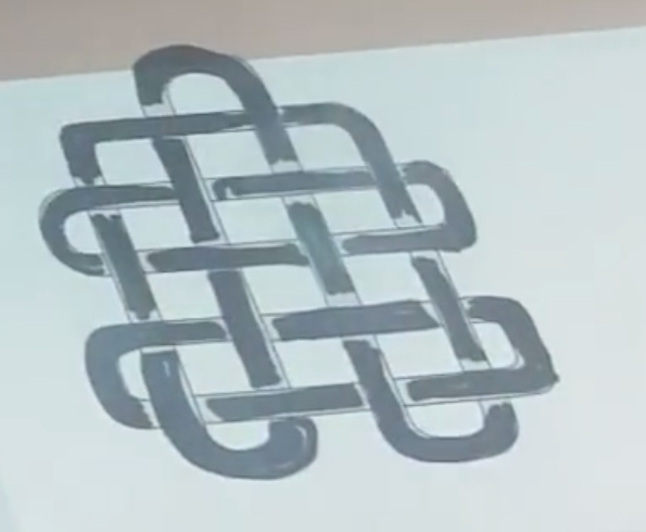
Im not really concerned about the ‘blockiness’ of the appearance. Its the inconsistency of the width of the lines from one row to the next. In the photo I posted above youll see in the vertical section every other line is siginificantly shorter than the prior horizontal line, leaving it looking like a comb when the source material shows a fairly straight vertical line:
The drawing is made into a digital file by the camera system. It should be a matter of just clicking one button to get a vector outline instead of an engrave fill.
In NY I will try and push for them to run an engrave + vector on a drawn image for me. Since they have done a smiley face cut out instead of engrave, I would say it absolutely is available already. Maybe @dan or another staff will do a sample of engrave at low DPI with and without vector outlines and post some high res images for us?
The source of the jagged edges is the laser turning off as it heads over to the next location to be cut. It takes some amount of time for the laser to stop producing an output, but the head is still moving, so you see the dwindling output as sharp points that still engrave in the material. (each point is the center of one pass, it is not one pass goes long and the next pass goes short)
If the head would stop briefly whenever turning off, you could avoid the jagged edges, but there would be minor divots all along your inner edge, and total engrave time would take longer.
1 Like
If that were the case, would every line not have the same issue? It seems to be happening on every other line, and only in certain areas
2 Likes
Yeah, I just looked really close at the original image after posting that comment, and noticed that you only get the points along a large vertical line. For the areas where the horizontal lines were not perfectly horizontal there is no tail.
So I am quite likely wrong in the above post. But that puts me back to very confused as to how these tails are being formed, which is uncomfortable.
2 Likes
There’s three things going on:
- “Steps” on the edges
- “fingers” on the edges
- Wavy lines that separate & then reconnect
The first one is just a function of being in low res/draft mode. The second two relate to a host of work we have in the hopper to make low-res engraving better - both are known items.
We won’t be doing any special requests at MFNY, I’m afraid; we don’t want to do anything to slow down the 1h+ wait times we expect.
6 Likes
There’s a separate outline drawn around the colored-in portion in several places in the original drawing.
My guess is - the auto-trace might have had trouble interpreting whether the artist desired that area to be filled in or not.
You’ll notice that where the logo is colored in solidly, the engraving appears to be more even.
It is actually bobbling exactly where it is supposed to, according to the drawing - that’s a good trace.
6 Likes
So, what happened was that I printed out an image (this image). However, the light gray shading was causing issues as it only picked up the outline very lightly. So one of the Glowforgers (I can’t quite remember who, I think it was @krodriguez ) was kind enough to take a sharpie to it so it would show up better. So that explains the irregularity of the drawing.
4 Likes
Yep…that would do it! (nothing wrong with it, but it explains some of the issues we see with the trace)
Thanks for filling us in! 
One thing that i mentioned in a couple of the tutorials was the need to have really clear delineations between dark and light, because cameras just can’t see between them clearly enough if there are a lot of shades of gray.
That new image is kind of light, so the camera might not have been able to pick it up real well. Darkening it is the way to go.
(Pencil drawings usually have a lot of issues with auto-traces too. They’re just too light for the cameras to pick up.)
(BTW: Black and white gives the best trace.)
2 Likes
My real concern was not what the user was doing incorrectly, but why the laser would ever interpret something to be drawn that way in the first place.
If it was an end user issue it would be easily fixable, but I can’t think of anything a user could accidentally do to get such precise distortions.
As it’s an interpretive issue in the renderer I’m guessing, I was hoping it was something still in the process of being refined. I’m glad they’re aware of it and I’m curious to know what the cause of it was
If they made a YouTube show about all the things they were working on and build process details I would watch it end to end. Build videos are the best.
4 Likes
I see it. Clearly the laser is not starting and stopping precisely.
My guess would be that the “long” lines (on, say, a right edge) are passes that were lased from left to right and the short lines are passes that were done from right to left. I don’t have the patience to look all that close at the moment, but I bet all the lines that appear to be too long on the right edges are the same lines that appear to be too short on the left edges.
An easy cause could be good ol’ backlash. When the head is moving left to right it thinks it’s a fraction of an inch ahead or behind of where it really is. Then it thinks the opposite in the other direction. The result is a comb pattern with a spacing of 2x the backlash (right?).
The belt and pulleys shouldn’t be introducing any backlash. Could the motor be consistently losing a step or two at every direction change? Maybe a pivot point on one of the pulleys is not rigid enough?
2 Likes
I’m also thinking this is the case. Belt drive with a cutting head of virtually no load (unlike the load forces of a CNC router) not going to create any level of measurable backlash.
From my limited understanding and use of bi-polar stepper motors, if the motor were to “lose” a step or two, the rotor would be out of phase with the pulses that drive it and the motor would just sit there and jitter (very unsettling to see your motor doing that). I’ve experienced this when I drive a bi-polar stepper motor past its max speed capability as an example.
Different issue though if the software is somehow missing a step or two between it sending a command to increment a step(s) and the controller sending the command to the stepper motor. The software has to check the controller to see if it has issued pulses to move the requested number of steps. On the firmware on the bipolar steppers motor controllers I have used, the controller updates its “current position” register every certain number of milliseconds (in the case of my controllers, 8 ms). This can be an issue for directional changes as the app software can do a lot of things in that 8ms between when the controller reaches the destination step and when it updates its “current position” register for the app software to obtain. Well, it was a problem for me until I figured out what was happening and added a few lines of code to compensate for it.
There is no “bio feedback” between the controller and the motor to know where the motor actually is, the controller only knows where it told the stepper to go.
Geeze that sound confusing to me as I read it. . .
1 Like
All you need to produce backlash with a stepper motor is friction. The torque it produces is proportional to the displacement from its target position. I.e. at the target position it is zero, so it can stop short or overshoot with a small displacement giving a torque equal to the static friction. Since you cant have zero friction there will be some finite backlash, hopefully very small in a well designed system.
Also it is easy to get backlash with belts and pulleys if the tooth profile is wrong.
1 Like
Can someone with a K40 and someone with an Epilogue post close ups of raster engraving at different resolutions to demo some of the things we are discussing here? Something that demonstrates the state of the art so to speak.
3 Likes
Hopefully they are doing some documentation videos as they work. Even if they don’t release them until shipping starts, or until the first chinese clone hits the market. The ad revenue from everyone pouring over the details we weren’t privy to after the fact cannot be insubstantial.
The lowest my Trotec will let me go is 500 LPI. If I enter “1” into the field it automatically sets it to 500, but it seems like it’ll take anything higher than 500. For instance, 501 is apparently fine. I can do the test at 500 if you want.
Here’s something I engraved at 1000 LPI a while ago. I’m just posting this since I already had the image uploaded to the forum…
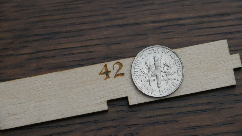
The coin in the second picture is a US dime (diameter: 17.91mm).
6 Likes
Regarding what is going on in low-res mode, here is a sample of what the top of a “2” looks like at various DPI (72, 300, 600, 1000) when magnified (with no anti-aliasing). This could probably be another thread in itself - but the first thing that comes to mind is CICO - crap in, crap out. Don’t expect magic from files that are low-res to start with.
72DPI

300DPI
600DPI
1000DPI
8 Likes
The more I think about it the more convinced I become that the banding is from backlash.
(as long as it isn’t a crap in crap out situation like @jbmanning5 showed)
The alternating overshoot direction is pretty easy to see in the name Allen in the photo posted above by @davidhknowles. Backlash will make it look like the laser is firing slightly earlier than it’s supposed to. That being the case, I’m guessing the top line of the “g” in “glowforge” was engraved moving from left to right. Is there a video of that engrave somewhere?
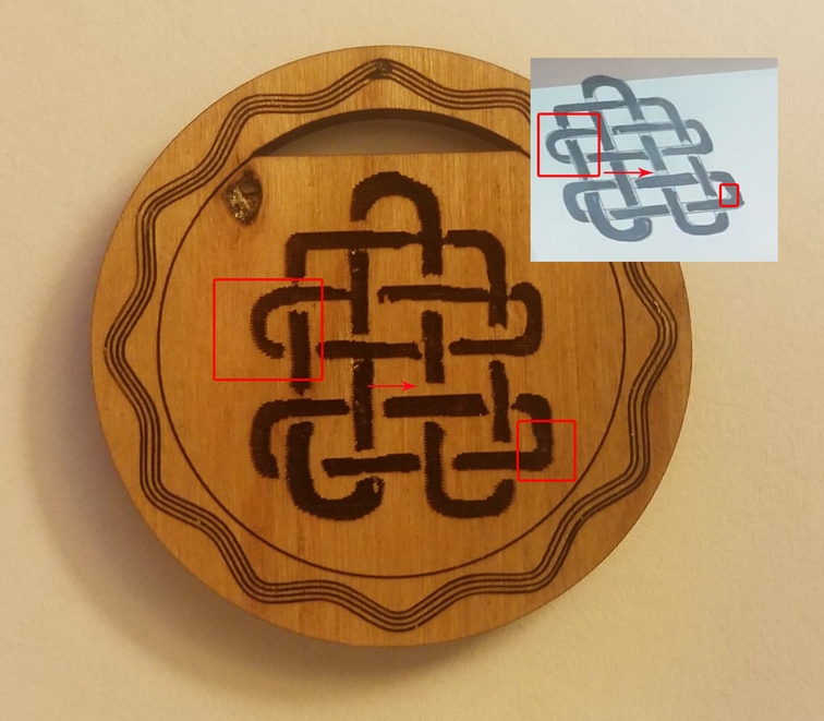
There is evidence of backlash in the wavy lines around the outside of the Celtic knot ornament(?) as well. As @GrooveStranger pointed out, the spacing is not even. If you watch the video you’ll see that the first wavy line that is scored the the outermost one and they work their way into the center. The first line is scored counterclockwise, then it changes direction and scores the second clockwise. It changes direction again, back to counterclockwise, to score the third line but then it scores the fourth line without changing direction. You’ll note that the spacing between the third and fourth lines is basically perfectly uniform.
I can’t quite tell, but I would bet that the spacing between the first and third lines is also pretty perfect, since those two lines were also scored in the same counterclockwise direction. So, if it wasn’t for line number two being scored clockwise, I think the wavy lines would have looked totally uniform.
Thankfully, mitigating backlash in hardware is pretty straightforward.
According to the specs: “Positioning precision to 0.001” (0.025mm)”, which is about an order of magnitude less than the kerf. I took that to mean positioning accuracy but I am beginning to think it is just the resolution if backlash is visible. So what is the positioning accuracy? This may be a show stopper for me.