Beta day - five (Fitted Gauge Box)

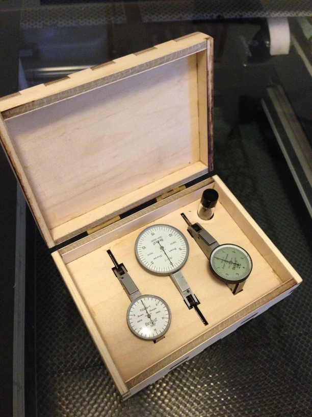
I have a number of these dial test indicators (DTI). They are used when doing machining to measure or compare extremely small distances and are delicate and quite expensive. These in particular are some of my favorites, but I don’t have a safe way to store them.


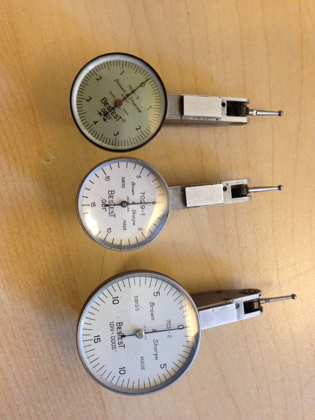
I decided a box was in order, and started by measuring the measuring tools to see how much room they wanted around them and how best to hold them in the box. I also decided I wanted a spot for a little vial to hold spare measuring tips (they come in different flavors for different applications).

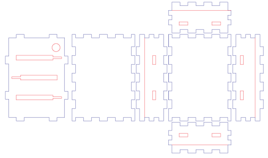
To get the basic box I used the http://makeabox.io generator from Glowsmith @kigster. It worked great for this application and the symmetry of the notches made a big difference later. I brought the PDF it made into Illustrator for further manipulation and in short order had something that looked like this.

A piece of (nominal) 1/4” plywood goes in the Glowforge and out comes… a beautifully cut big fat failure.


I had messed up the drawing in a number of ways, and none of the pieces wanted to fit together (bonus points if you spot the error).

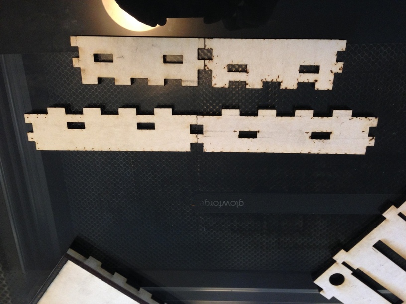
Plus I had cut the lid sides down so far that there was nothing to lock them together.

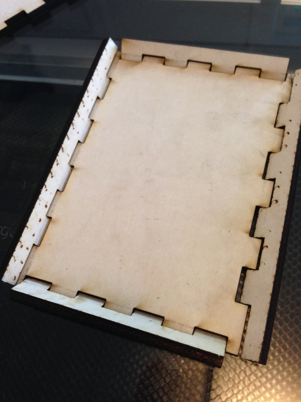
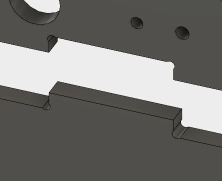
And finally when drawing the slots I missed a small protrusion on each DTI so they did not fit at all.
Back to Illustrator for a fix up and the next round looks like:

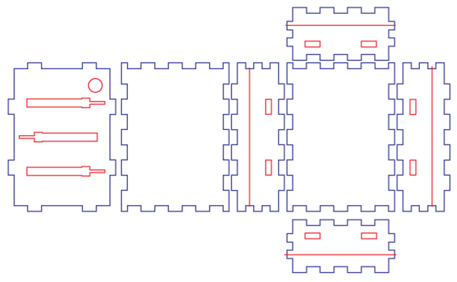
Small visual changes maybe, but the devil is in the details. One key here was that since the sides are all symmetrical I could fix two of them and just copy them, a big time saver!
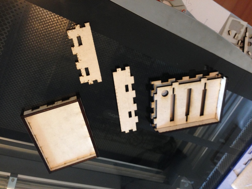
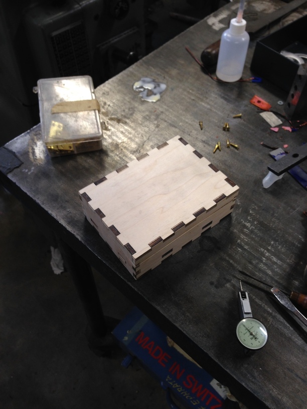
This one worked great, and I also tweaked the settings I was using a bit to get less char on the edges.

Peeling off the transfer paper took longer than cutting the box out, but the surfaces stayed nice and clean.


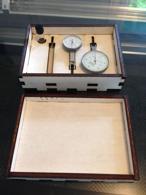
Notice there are only two in there. I made one more bozo move by only measuring the bodies of two (which are the same) and assuming all three were the same size. They are not.
I was in a hurry to finish before I had to start cooking dinner, so I just punted, glued it up, and screwed on some little hinges.

I am pretty sure that with a little sanding I can get the .0001 DTI to fit in its slot, but I need to find a latch, and I should probably take the hinges off and put some poly on it to keep it cleaner. Overall I am really happy though since these guys have been banging around in a drawer of my toolbox for way too long.
It is almost as nice as the Quiet Year box by @Kusmeroglu

One thing I think is worth looking at in order to make better box joints is a trick I saw on the Ponoko blog. If you put a tiny circle inside each notch, the end result is a much tighter fit.

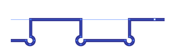
@kigster are you up for that challenge? :slight_smile:

More (not quite so specialized) storage related things to come…

45 Likes

The circles in the edge of a joint are referred to as dogbones. Common practice in the CNC world.

9 Likes

I should have known they would be a standard practice, I don’t have much current CNC experience.
Great name for them too.

3 Likes

I’m glad you included a couple of circles in your design - they are impossible to cut perfectly with a knife, and i plan to put the GF to good use on them…great looking case. :relaxed:

1 Like

Oh my gosh! This looks great! I really love that you also used software created by another person in the forum.

Does the error have to do with the square cut outs in the middle of the side pieces? They should have been at the same height/level on the too long ones and then at the same height/level on the two short ones? It looks like one higher and one lower on both longs and both shorts (whoa, this is difficult to explain).

Thanks for showing and explaining the whole process. This is an awesome tutorial!! Fabulous work, Josh!

4 Likes

This was a great little series. I don’t know about the designing part (yet), but still was fascinated by the entire process. Thank you!

2 Likes

Bingo. That is what I got for rushing. :frowning:

2 Likes

Love the box, love the dial indicators. The dog-bones confuse me though as I was lead to believe that they are unneeded when laser cutting due to the small kerf?

5 Likes

I was thinking the same thing…I understood they were useful for doing cnc dsince you coukdt get a straight corner do to the bit being round…Ive never used them when laser cutting and the joints fit just fine…

1 Like

For hinges, cut pilot holes for the screws? Even just small ones to have a mark for drill bits? Maybe too much work for a one off box, but should make assembly easier if you make a bunch…

5 Likes

How so? is it an interference thing because you don’t actually have sharp corners?

The use of “dogbones” is interesting. I use them in my CNC router cuts because a round tool can’t cut a 90° internal corner and, unless you want to make an oversize slot, or tab, or file the corners after cutting, some adjustment has to be made for the tool radius. Does your use of dogbones mean that the GF is “rounding” the internal corners, as @nick07lee implies?

I’m not certain the dogbones need to be the “Mickey Mouse Ears” your diagram suggests, just a little will do …

3 Likes

Great picture. That’s more similar to what i have seen in my neck of the woods.

And if you have pieces butting up (like in your picture) you can round the external corners and save a little time. (ps is that solidworks and do you have a box exploded flat?)

Corner reliefs are useful for various manufacturing processes.

In 3D Printing, it’s very difficult to achieve a perfect internal 90 degree corner. The tool head need to decelerate to a full stop in one axis and then accelerate in the other direction, while doing this it tends to ooze. So, for internal corners, good design practice is to put in a notch to minimize the effect of the ooze on the part geometry:

Other times, putting corner reliefs into the part prevents you from having a sharp corner in the forming tool, where the stress concentrates (and will wear down first). Here is the same 3D printed part (lower vertex of a Kossel 3D printer) as a machined aluminum extrusion piece. Also note that the 4 corners in the square hole for the OpenBeam extrusion is reliefed with corner relief radii:

That being said, the reason for putting that edge relief in laser cutting isn’t for fit; it is there for stress relief. In acrylic, if you left that internal corner sharp, the sharp inner corner becomes a stress concentrator and will eventually start fracturing there. (Not as much of a problem with wood).

Here’s more info.

-=- Terence

26 Likes

Wonderful box, and thanks for showing us the process, warts and all! Only one thing missing, and that is your fancy hieroglyphs on the lid. Are you saving that for another day?

4 Likes

Very creative @jkopel.
How long did that take to cut?

2 Likes

Awesome info…I just started working with acrylic for building things so this will definitly be helpful.

2 Likes

Awesome looking box. I especially like the dark edges which make a nice contrast. Thank you for sharing.

5 Likes

Here’s the Ponoko blog post about the little circles:

They are mainly discussed as a method of transferring force evenly away from a sharp corner to avoid material cracking.

Effectively a sharp corner is creating a weak point in the acrylic. Not good when this is structurally an important part of the design. A small radii in that corner does wonders to transfer the forces from one face of the hole or slot to the other and reduces the risk of the material splitting at the corner.

14 Likes

:thumbsup: A lot of really great reference materials in this thread, but I’m out of likes for the day…Gonna bookmark.

2 Likes