We’ve seen the videos for drawing on acrylic and drop and drag a graphic file.
I’m certain I’m not speaking solely for myself here when I ask if it would be possible to see a video of the workflow from a DXF based drawing through cut and measurement of results (for accuracy) of a reasonably simple part? I have just the perfect little 3.25" part in DXF format created in fusion 360 that I’d offer to supply. Just cutting, no engraving component.
A similar workflow for SketchUp files would be greatly useful for me as well. I saw SketchUp files mentioned previously, but I haven’t seen them mentioned in any of the videos I’ve seen. I’d love to know more details about how I can specify cutting vs engraving within a SketchUp file (preferably at different levels so I can engrave at x% and y% in the same print).
You’d take the DXF and either pass it thru Adobe Illustrator or Inkscape and use the plugins provided by Glowforge.
Ironically I asked for the same thing a couple weeks ago (I proper demo of GF working with AI.) In the video posted a couple days ago, the person had AI already opened and they loaded a pre-canned file then passed to the GF plugin. I wanted to see a more complex vector either made and pre-canned by explain how cutting, engraving and this ‘out of focus’ function that keeps getting mentioned and not demoed. Or They can just demo one of the items they they slideshow on the GF main page.
When I was at the Glowforge open house last week I had a chance to chat with an employee about the current state of the software.
He told me that although they had made a lot of progress it was still not complete.
I would hope that as it gets closer to “done” we will see more specific demos of how to use it and the various workflows it will support.
In the mean time I am gleaning as much info as I can from the various “official” responses on threads here.
for instance, I am not sure that you would need to “take the DXF and either pass it thru Adobe Illustrator or Inkscape” since @dan has said that they will be supporting DXF directly.
Of course one of the great things about cloud based code is that it can be continuously improved and updated over time. So in that way it is never really “done”, and they can add new functionality as it is suggested/developed!
So I suppose my takeaway from the above comments should be that DXF ==> GF direct is not part of the functionality at this point despite the inferences to the contrary on the website. . . but we are hopeful?
We’re not importing DXF directly yet but plan to. That said we’ve found the format to be so poorly specified that we’re not sure how well it’ll turn out.
I hear you @dan. I know if you use one of the many file conversion utilities (STL => DXF) you get a DXF with all the ugly triangle representation DXF looking part when loaded into something like AI. But, while I can’t comment on the “specification” specifics, when you save directly to a DXF from fusion 360 (in my case), you get what looks to be a perfect line drawn representation of the part with the precise dimensions for each feature. I say precise dimensions as when I load that resultant DXF into my MeshCAM CAM software, all the part features are precise to the original CAD part once machined.
Lasersaur “supports” DXF, but only R14 with lines and polys. So far Rhino is the only program able to export this special version, at least as far as anyone in their semi-large community seems to have figured out.
Is there any program which can only generate in DXF, or some advantage to using the file system? I have only ever heard complaints about it. Never any advantages.
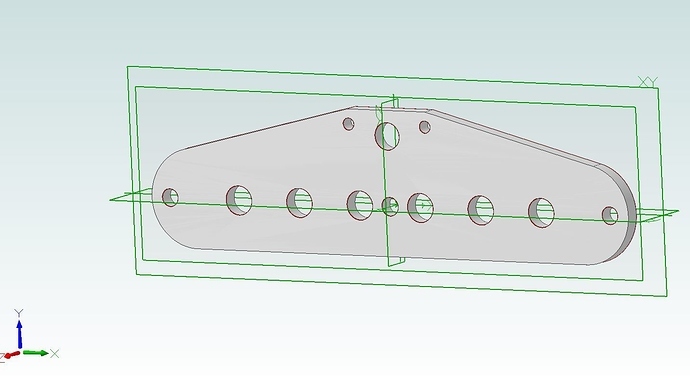
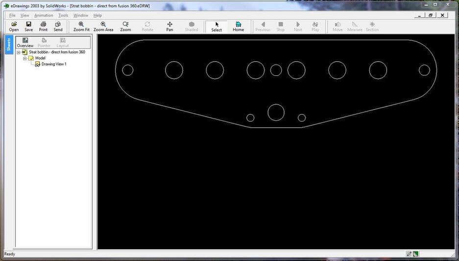
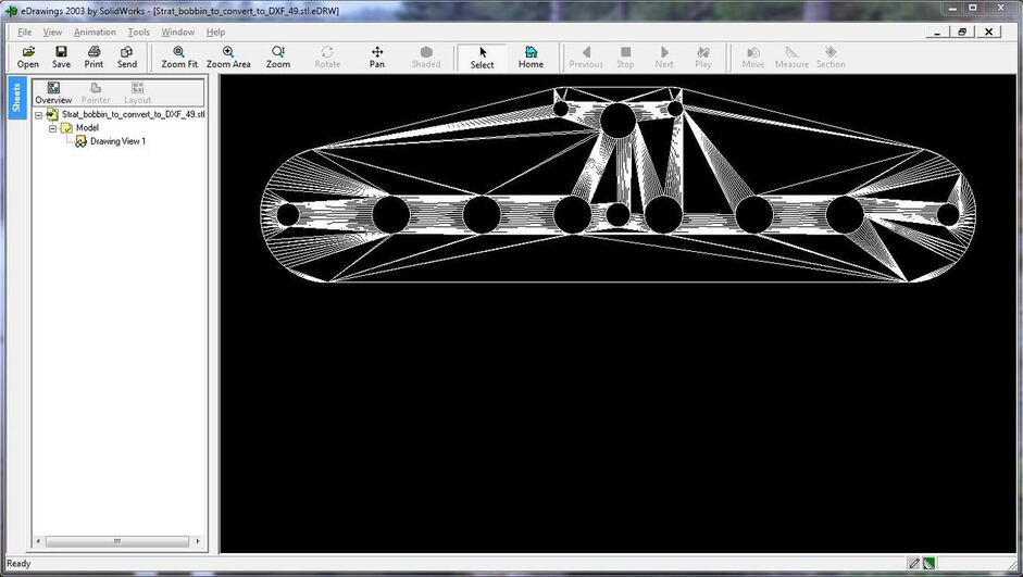
Autodesk fusnion 360 can directly output a DXF. Below are 2 examples, the first a direct save to DXF and the second a direct save to STL then converted via internet utility to DXF. Both were from the same part in fusion 360.
Again, both from the same version of the same part in fusion 360. Quite the different result when viewed in the drawing app, but both are perfect when imported into my CAM program (MeshCAM).
DXF is about 30 years old, and is showing its age.
The only real advantage is has it that everything supports it (if only sort of), and it was designed to handle CAD data natively in ASCII and in a “human readable” fashion. Until they introduced the binary version anyway.
It is essentially open, so it makes possible a lot of edge case conversions from other software. Things like vector map data from GIS systems are often in crazy proprietary formats, but that software will almost always spit out DXF. It is the lingua franca of 2D like STL is for 3D. They both suck, but everyone uses them.
It seems that SVG or even PDF is a much better option for import into the GF, and there are plenty of online file conversion utilities that will do the work for you, but some native support of DXF would still be a good addition to the workflow.
The reason those two examples are so different is that STL is not designed for use with 2D drawings and DXF is.
STL is intended for the representation of surfaces, and it requires that all the geometry be defined as triangles, and that is ALL is understands. DXF is a much more complicated format and it understands things like lines, arcs, polygons, etc. Some versions of DXF even support complex 3D constructs, but not all of them.
You should really only use STL where it is appropriate, such as the final step before moving to CAM or a slicer for 3D printing. If you use it at any earlier point you are throwing away useful information.
I too would like to see the workflow for going from a CAD part design to GlowForge interface. For my CNC mill, I can read a DXF file into my CAM software and generate toolpaths from that. It seems like the GlowForge process should be similar. Why would we need to go through Adobe Illustrator?
Agreed. The GF is a very, very cool and sophisticated piece of technology that looks to dumb down the software to the lowest common denominator. I get it, they want to bring this technology to the cottage industry and the masses in general. But it would benefit greatly from be the capability to use traditionally generated CAD parts code. You see this in a couple of the CNC router products (e.g. Inventibles, Carbide 3D) which have the dumbed down apps for the masses, but allow for user CAD/CAM generated g-code interfacing for more detailed precision parts design (not to imply that I know more than the most minute bit of CAD/CAM). It seems like such a natural to have a tool like the GF that is ultimately g-code driven to allow for that industry standard workflow to be somehow incorporated into the product. Keep the best of the things like the locationing camera technology to be combined with that traditional workflow for CNC as well as the simplification app. Hopefully this will find its way into the GF development. Either way, I’m sitll in for the Pro.
I’m not sure about raster type engraving, but straight cutting or outlining only needs lines to define the toolpath. Raster engraving sounds like be similar waterline cutting on a CNC mill - that is you are just cutting away anything inside a boundary of some sort. I suppose a 3D raster with different levels might be different, but there are waterline analogs to that as well.
I think your analogy is correct, and vector cutting is essentially identical to a waterline approach with a fixed tool diameter (the laser spot size). So if you have a colored or layered vector regardless of the format it is derived from you can assign power (and speed) values to each color/layer so that the result will be varied in depth. You can define cut paths (follow this line) and engrave paths (cut this entire area at one power level) and off it goes.
Rasters are different since a raster image is just a matrix of data (i.e. pixels) and each pixel can only carry a numeric value. When engraving a raster it appears that the Glowforge software will simply apply a power level to each numeric value (and interpolate down to get a maximum of 256 levels). So, say you have a grayscale image, then the laser applies maximum power to pure black pixels, no power to pure white pixels, and power relative to the darkness of gray for everything in between. It is not clear to me from watching the available video if it does so in multiple passes (i.e. cuts the same area over and over to achieve the final depth in a waterline approach) or if it pulses the power level to approximate the color at each individual pixel. It will be interesting to find out as more information becomes available.
I can say that when I was at the open house I watched the scanned items being engraved, and the software was clearly taking the raster from the camera and thresholding it to get a solid area. My take is that the software may be doing a smooth and threshold kind of operation to reduce the levels of gray down to 255, and in the demos the threshold was set to just two levels (i.e. black and white). The software that is generating motion planning from rasters also seems to have a notion of “cut the outline when you are done engraving” by following the outermost detected edge.